Transcription of Bolting Procedures - nibtorque.com
1 6 of 12 Bolting Seminar Bolting Procedures As mentioned earlier, the best way to obtain uniform bolt loading is by following well documented Bolting Procedures . Regardless of the equipment used to load the bolts in a joint, a prescribed method for doing so is of the utmost importance. Developing good Bolting Procedures can be a monumental task if you do not establish some criteria. A procedure for Bolting should include specific instructions for: 1. Joint, bolt and Gasket Preparation 2. Method of Applying Torque or Tension 3. Documentation of Results The following is a sample Bolting procedure using a manual or hydraulic torque wrench: CASE I Bolting PROCEDURE MANUAL OR HYDRAULIC TORQUE WRENCH THIS PROCEDURE IS TO BE USED IN THE FOLLOWING SITUATIONS: 1. Joints in vibrating service. 2. Joints in cyclical service. 3. Joints with ring joints or solid metal gaskets of SOFT IRON. THE FOLLOWING DATA, TO BE RECORDED ON THE JOB DATA SHEET.
2 1. Unit 2. Joint Identification and Alignment Check 3. bolt Material 4. bolt Diameter 5. Number of Bolts 6. Nut Size ATF 7. Gasket Type 8. Gasket Material 9. Condition of Bolts 10. Condition of Washers 11. Lubricant 12. Torque Wrench Data 13. Torque Settings 14. Friction Factor (K Factor) 15. Percentage of Yield 16. Date and Time Initial Tightening Completed 17. Date and Time Final Tightening Completed 18. Completed Alignment Check 19. Supervisor's Signature 20. Notes 7 of 12 Bolting Seminar Sample Bolting Procedure (Continued) JOINT PREPARATION 1. Thoroughly clean the flange faces and check for scars. 2. Check studs and nuts for proper size, piping material specifications and cleanliness; and any rust, paint or corrosion to be removed by wire brushing or bead blasting. 3. Remove burrs from all threads. 4. If one stud is replaced, all must be replaced. 5. Gaskets are to be checked for proper size and specifications.
3 Metal gaskets to be free of grease, rust or burrs. 6. Check flange spot face where nut makes contact. This area must be clean and smooth. Use 1/4" thick hardened steel washers on both ends of studs when installing new bolts. 7. Check flange alignment: alignment of parallelism tolerance shall be limited to 3/32" per foot of pipe diameter measured at any point on the flange circumference. 8. Number the studs and nuts for identification and control during Bolting procedure. 9. Lubricate the thread area of both stud and nut. Also lubricate the face of the nut in contact with the flange. Apply lubricant thoroughly to all surfaces. 10. Where applicable, the flanges will be pulled together and snugged with hand wrenches. When working with heavier flanges that have no support, it is acceptable to use an impact to lightly snug a maximum of 8 bolts beginning with bolt #1 and following the bolt pattern. NOTE: When using an impact wrench, only enough pressure shall be applied to hold the flange stable.
4 TORQUING PROCEDURE 1. Fill in the blanks on the Job Data Sheet showing 30%, 70% and 100% torque values. 2. Set the torque wrench to the 30% torque value and apply the torque wrench in the criss-cross pattern for that particular flange until all bolts have been tightened once. 3. Set the torque wrench to the 70% torque value and repeat step 2. 4. Set the torque wrench to the 100% torque value and repeat the criss-cross pattern a third time. Check all bolts at 100% torque with a circular pattern. 5. A final circular pass will be made with the torque wrench set at 100% torque value 24 hours after the third pass is completed on joints with spiral wound or double jacketed gaskets. 8 of 12 Bolting Seminar Sample Bolting Procedure (Continued) CASE I JOB DATA SHEET FOR USE WITH HAND OR HYDRAULIC TORQUE WRENCH 1. Unit _____ 2. Flange _____ Starting Alignment Checked _____ 3. bolt Diameter _____ 4. bolt Material _____ 5.
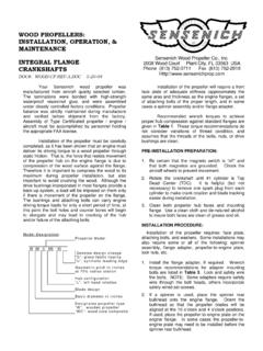
5 Number of Bolts _____ 6. Nut Size ATF _____ 7. Gasket Type _____ 8. Gasket Material _____ 9. New Bolts _____ 10. New Washers _____ 11. Lubricant Manufacturer _____ Lubricant Name or Number _____ 12. Torque Wrench Data: Manufacturer _____ Model _____ Torque Range _____ Ft-Lbs. to_____ Ft-Lbs. 13. Torque Settings: First Pass at 30% _____ Ft-Lbs. Second Pass at 70% _____ Ft-Lbs. Third Pass at 100% _____ Ft-Lbs. Fourth Pass at 100% _____Ft-Lbs. 14. Friction Factor _____ 15. Percent of Yield _____ 16. Third Pass Completed: Date: / / Time: _____ 17. Fourth Pass Completed: Date: / / Time: _____ 18. Completed Flange Alignment Checked _____ 19. Supervisor's Signature _____ 20. Notes: 9 of 12 Bolting Seminar Bolting Procedures - Alignment FIGURE 7 1/32' GAP Item 7 of Joint Preparation in the previous example mentions "alignment of parallelism tolerance". The three sets of flanges in the diagram above are three examples of such tolerance.
6 Joint number 1 is in alignment. Joint number 2 is not in alignment. Notice that the gap at the top of the flanges is 5/32" and the bottom 1/32". When we subtract the bottom gap from the top gap the solution is 4/32" (5/32 - 1/32 = 4/32). This number is greater than the allowable tolerance 3/32". Therefore, the flanges are considered not to be within the parallelism tolerance. Joint number 3 is within the parallelism tolerance, but there may be problems when trying to install the bolts. The holes in most flanges will allow 1/8" clearance around the stud. Joint number 3 is offset by more than this amount (1/8 = 4/32 and 5/32 > 4/32). If the studs do not slide into the holes of the flanges without interference, do not force them! Thread damage may result. When assembling a joint, always make sure that the bolts, gasket and flanges are not forced into place. Damage to any of these components could result in unsealable leaks.
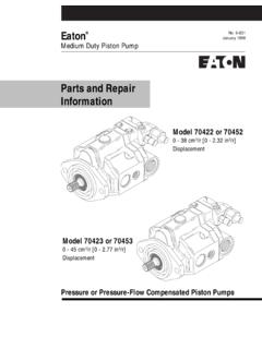
7 Bolting Procedures - Lubrication Lubricating the bolt was mentioned earlier as one of the variables that would reduce the K Factor. Actually, just lubricating the bolt is not enough. The lubricant must be the correct one for the bolt material being used. It must also be able to withstand the temperature and pressure to which it will be subjected. A lubricant is not effective if it breaks down or is pushed out from between the threads of the fastener. It must remain between the threads, nut faces and washers to be effective. TABLE 1 CONDITION OF BOLTS K FACTOR REQUIRED TORQUE New Xylan Coated Bolts with Moly Paste and Hardened Steel Washers 926 Used Xylan Coated Bolts with Moly Paste and Hardened Steel Washers 1,027 New Bolts with Moly Paste and Hardened Steel Washers 1,076 Used Bolts with Moly Paste and Hardened Steel Washers 1,468 Used Bolts without Lube or Hardened Steel Washers 1,957 The bolts used to obtain the K Factors in Table 1 are B7, 1-1/2" studs.
8 The lubricant is molybdenum disulfide paste containing at least 70% solids. 5/32- Difference