Transcription of THERMOPLASTIC FLANGES - iploma.com
1 TECHNICAL INFORMATIONWEIGHTS & DIMENSIONSJuly 9, 2004 SUPERSEDES ALL PREVIOUS EDITIONSTHERMOPLASTIC FLANGESFL-4-0704 Visit our web Quality PolicyIt is the policy and objective of Spears Manufacturing Company to produce a superior quality product suitable for its intended use, with regard to functionality, structural integrity and conformance to established industry standards and practices. It is the commitment of this Company to do so in a manner which provides consistency of product quality, optimum availability, and superior customer service, while maintaining efficiency of operations and profitability necessary to perpetuate product improvement and customer satisfaction. Furthermore, it is recognized that the attainment of these objectives is the responsibility of all Company operations and personnel according to their respective information contained in this publication is based on current information and product design at the time of publication and is subject to change without notification.
2 Our ongoing commitment to product improvement may result in some variations. No representations, guarantees or warranties of any kind are made as to its accuracy, suitability for particular application or results to be obtained therefrom. For verification of technical data or additional information not contained herein, please contact Spears Technical Services Department [West Coast: (818) 364-1611 East Coast: (717) 938-9006]. Additional Technical PublicationsTHERMOPLASTIC VALVES PRODUCT GUIDE & ENGINEERING SPECIFICATIONS ..V-4 PVC SCHEDULE 40 FITTINGS WEIGHTS & DIMENSIONS ..40-4 PVC SCHEDULE 80 FITTINGS WEIGHTS & DIMENSIONS .. 80-4 CPVC CTS FITTINGS &VALVES WEIGHTS & DIMENSIONS ..CTS-4 PVC INSERT FITTINGS WEIGHTS & DIMENSIONS.
3 INS-4 THERMOPLASTIC FLANGES Contents PageGENERAL INFORMATION Recommendations For Installers And User ..1 bolt Torque ..1 Torque Sequence ..2 Gaskets ..2 flange Make-Up ..2 Configuration Terminology ..2 PVC & CPVC INJECTION MOLDED CLASS 150 IPS FLANGES Technical Information Application ..3 Pressure Ratings ..3 flange Types ..3 Materials ..3 Conformance Standards ..3 Weights & Dimensions ..3 PVC FABRICATED CLASS 150 IPS AND PIP FLANGES Technical Information Application ..9 Pressure Ratings ..9 flange Types ..9 Special Note on PIP flange Sizes ..9 Materials ..9 Conformance Standards ..9 Weights & Dimensions ..10 THERMOPLASTIC FLANGES1 SPEARS MANUFACTURING COMPANYGENERAL INFORMATIONR ecommendations For Installers And UsersPlastic piping systems should be ENGINEERED, INSTALLED, and OPERATED in accordance with ESTABLISHED DESIGN AND ENGINEERING STANDARDS AND PROCEDURES for plastic piping systems.
4 Suitability for the intended service application should be determined by the installer and /or user prior to installation of a plastic piping system. PRIOR TO ASSEMBLY, all piping system components should be inspected for damage or irregularities. Mating components should be checked to assure that tolerances and engagements are compatible. Do not use any components that appear irregular or do not fit properly. Contact the appropriate manufacturer of the component product in question to determine : Spears Manfacturing Company DOES NOT RECOMMEND the use of THERMOPLASTIC piping products for systems to transport or store compressed air or gases, or the testing of THERMOPLASTIC piping systems with compressed air or gases in above-and-below-ground locations.
5 The use of Spears products in compressed air or gas systems automatically voids Spears warranty for such products, and their use against our recommendation is entirely the responsibility and liability of the installer. Spears Manfacturing Company will not accept responsibility for damage or impairment of its products, or other consequential or incidental damages caused by misapplication, incorrect assembly, and/or exposure to harmful substances or Weld Connections Use quality solvent cements and primers formulated for the intended service application, pipe size and type of joint. While the pipe and fitting materials may be compatible with the intended medium, the solvent cement may not be.
6 Consult the manufacturer for suitability of use. Read and follow the cement and primer manufacturers applications and cure time instructions thoroughly. Be sure to use the correct size applicator. Threaded Connections Use a quality grade thread sealant. WARNING: SOME PIPE JOINT COMPOUNDS OR TEFLON PASTES MAY CONTAIN SUBSTANCES THAT COULD CAUSE STRESS CRACKING TO PLASTIC. Spears Manufacturing Company recommends the use of Spears Blue 75 thread sealant which has been tested for compatibility with Spears products. Please follow the sealant manufacturer s application/installation instructions. Choice of an appropriate thread sealant other than those listed above is at the discretion of the installer. 1 to 2 turns beyond FINGER TIGHT is generally all that is required to make a sound plastic thread connection.
7 Unnecessary OVERTIGHTENING will cause DAMAGE TO BOTH PIPE AND FITTING. bolt TorqueRecommended bolt Torque is shown in Table 1. Threads should be clean and well lubricated. Actual field conditions may require variations in these recommendations. CAUTION: UNNECESSARY OVER TORQUING WILL DAMAGE THE Size (in.)Recommended Torque(ft. lbs.)1/2 - 1-1/2122 - 4255306 - 8401064129514 - 24110 MADE IN THE 2 THERMOPLASTIC FLANGEST orque SequenceBolt Torque sequence is shown in Table faced, 1/8 thick elastomer gaskets with a Shore A Durometer of approximately 70 is Make-upOnce a flange is joined to pipe, the method for joining two FLANGES is as follows: A.
8 Piping runs joined to the FLANGES must be installed in a straight line position to the flange to avoid stress at the flange due to misalignment. Piping must also be secured and supported to prevent lateral movement which can create stress and damage the flange . B. With gasket in place, align the bolt holes of the mating FLANGES by rotating the ring into position. C. Insert all bolts, washers (two standard flat washers per bolt ), and nuts. D. Make sure the faces of the mating surfaces are flush against gasket prior to bolting down the FLANGES . E. Tighten the nuts by hand until they are snug. Establish uniform pressure over the flange face by tightening the bolts in 5 increments according to the sequence shown in Table 2 following a 180 opposing sequence.
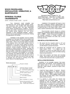
9 F. Care must be taken to avoid bending the flange when joining a Spears flange to a raised face flange , or a wafer-style valve. Do not use bolts to bring together improperly mated TerminolgyMulti- bolt Pattern Ring bolt hole drilling accepts ANSI and Metric FlangesSoc Slip socket connection for solvent cement weldingSpigot Pipe connection for solvent weldingFipt Female Iron Pipe ThreadSR Fipt Spears patented Special Reinforced (SR) plastic threadIPS Iron Pipe SizePIP Plastic Irrigation Pipe 3 SPEARS MANUFACTURING COMPANYPVC & CPVC INJECTION MOLDED CLASS 150 FLANGES ApplicationMolded CL 150 flange fittings are coupling devices designed for joining IPS (Iron Pipe Size)
10 Plastic piping systems, where frequent disassembly may be required, and can be used as a transitional fitting for joining plastic to metal piping systems. Suitability of application is at the discretion of the Rating150 psi, water at 73 TypesOne-Piece available in socket configuration, sizes 1/2 through 8 ; thread and SR thread (special reinforced) configuration sizes 1/2 through 4 .Van Stone Style two-piece design with rotating flange ring, available in socket configurations, sizes 1/2 through 16 ; thread configurations, sizes 1/2 through 4 and spigot configurations, sizes 1/2 through 12 Blind closed ring design for capping off a mating flange , flanged fitting or flanged valve, available in sizes 1/2 through 12.