Transcription of GC Compact cat. - Galperti
1 GC - Compact FLANGES1 Engineering ENGINEERING is an International Company whose business is the design, manufacture and supplyof high integrity connectors, forged fittings and flow control , Gas, Power and Petrochemical Companies utilize our products in a variety of applications, where oftencomplex technical problems can now be solved cost order to focus our effort upon our Customer requirements, Galperti ENGINEERING offer a total design andmanufacturing capability, from our dedicated in-house forge through to finished product, a unique feature intoday s ever demanding global G-C Compact flange System has an estabilished record throughout the world, meeting or exceeding allcurrent industry codes and facility is accredited with ISO 9001 and our products meet all current industry G-C Compact flange System is a fully proven alternative to the conventional flanged connection used throu-ghout the oil, gas, petrochemical and power generation industries.
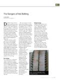
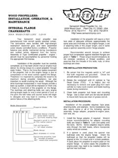
2 Produced in a comprehensive range of sizesand materials they offer versatility, compactness, weight saving and cost effectiveness in connecting Connector is designed to meet ANSI B , ASME VIII, API 6A/Q1 and other design codes. The designhas the approval of Lloyds, DNV and Stoomwezen. Fully fire tested in accordance with API 6FB parts 1 and gas tested to meet all aspects of ASME Chapter IX ( 1400 bar at 180 C Gas test with bending).G-C Compact flange System offer the following advantages over standard flanges: Easy Assembly Compact Construction Reduced Weight Metal to metal sealing technology re-usable Flexibility - seal rings, standard gasket etc. Full Design approval Cost saving Ability to with stand severe operating loads Smooth bore offers erosion reistance Face to face make up offers corrosion resistance2 Quality Type Approval & TestingGC Compact flange under pressure test - 10 9000 PSI3 Quality Type Approval & TestingHydro/gas bending tests on 12 2500#4G-C Advantagesstill able to meet all of the design requirements in and ASME VIII Div.
3 2. Pressure and temperatureratings are the same as those listed in ASME overall benefits of using the GC flange compared toANSI flanges and other pipe connectors are:Why use GC flange ? High sealing integrity dueto double seals Small dimensionsCompact design Much reduced weight Meet ANSI valveends requirements Reusable seal rings One seal ring per NPS(Nominal pipe size) Pressure, temperatureexternal load capacitiesavailable Standard bolts and ten-sion/touque tools Flush bore with no cre-vice Full face jointing elimina-tes opportunity for exter-nal corrosion bolt overstress cannotdamage seal ring orflange Self energised and pres-sure energised metal tometal area seal ring Maintenance free connec-tion with no periodicre-tightening of bolts. Weld overlay welding ofsealing area not neces-sary to bore seal (heel) Quich and reliablemake-upGC flange AdvantagesWHY USE GC flange CONNECTORS?
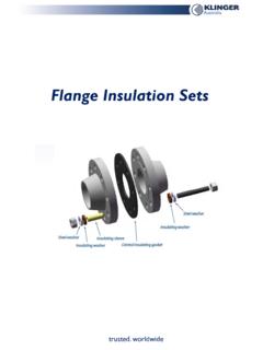
4 The Gaplerti Compact (GC) flange is a high performanceconnector developed by Galperti Engineering. Normallywith the strength and sealing integrity of a welded joint,the GC flange is lighter, smaller and easier to install thanan ANSI raised face or ring joint flange . The main cha-racteristic of the flange is the flange face geometry. It inclu-des a slightly convex bevel ( flange face angle) with thehighest point called the heel, adjacent to the bore. Duringmake up of the connection, the gap at the toe of the flangeis closed and flange face to face contact is closing of the gap at the flange toe is an indication ofcorrect bolt load has been applied during assembly. Addi-tional bolt tightening cannot overstress the GC flange has two seals, one seal, which is activatedby the pre-stress, , the heel seal and one self energisingand pressure energised seal, the Galperti Ring (GR)seal ring.
5 This unique double sealing system give superiorsealing performance over conventional single sealing GC flange achieves extremely high levels of perfor-mance by incorporating the most important concepts inpiping connector design: Sealseat the smallest possible diameter (to reduce pres-sure separation loads) Dual metal-metal sealing. Isolate the seal ring from piping loads and internal fluid(to maintain performance under changing conditions). Face to face contact after make-up and during normaloperation conditions-added GC flange uses the Galperti seal ring (GR) whichseals in the flange groove. The seal ring design is basedon design principles used for the well established G-Lokseal ring. The heel seal ensures a smooth bore with no cre-vice between the flange halves at the bore.
6 Furthermore, itreduces the area exposed by pressure to a minimum andkeeps the seal ring dry during normal operations. Com-pared to other single sealing systems, the heel seal isola-tes the GR from thermal shocks and corrosion attacks (boreseal carbon steel seal should have included corrosionallowance).Severe mechanical loads, especially dynamic loads, canrender conventional gaskets useless. The GC flange bringsthe flange faces into full contact while completely isolatingthe GR from mechanical loads. The GC flange withstandsexternal loads, where loads create yielding in the pipe andseparating the flanges while the seal remain of these concepts allow the GC flange to be more com-pact and leakfree than standard ANSI/ASME flanges yetFIGURE 15G-C AdvantagesGALPERTI ENGINEERINGE nhanced sealing heel which is ametal to metal axial area contact seal with no crevicebetween the flange halves and gives flush bore.
7 The reu-sable seal ring, which is a metal to metal radial area con-tact seal. One nominal size seal ring is necessary per pipesize independent of pressure class. This reduces the num-ber of seal rings sizes to a minimum. The GR seal is dryduring normal operation conditions and is removed fromthe piping and bolt loads creating a highly rigid connec-tion insensitive to mechanical design and fatigue strength exceeds the loading allowablefor the connecting pipe as limited by the applicable designcode. bolt stress variation of only 3-5% for any designload condition, preventing risk of bolt failure by pressure/temperature and external load capacitiesare available in the GC flange User manual that is avai-lable on life cycle costs due to reduce of investment costs,installation costs and low operating operating costs are low due to maintenance freedesign with the high reliability against leakage that redu-ces system downtime for offshore design suggests arequirement of two kilograms of structureto support one kilogram of deck GC Compact Flanges.
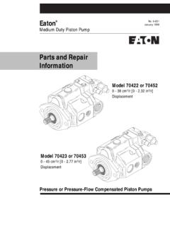
8 Weightsavings in the range of 60% to 80% com-pared to ANSI flanges are flanges are shorter and have smallerdiameters than conventional 1 compares GC and ANSI weldneck flanges assembly weights. Closepiping and hook-up arrangements withtypically 20% to 30% smaller 25% to 40% shorter and quick make-up light weight, small sizeand reduced bolting ensuring ease ofhandling and assembly. Reduced connec-tor size leaves more space for the opera-tor and the tooling, and the smaller dia-meter bolting allows lighter weight toolingto be used. bolt load up to 100% of desi-red bolt load first time reduced number ofbolting pre load controlled flange rotation (closing ofthe gap at the toe) gives a direct indica-tion of correct pre standard imperial bolts for strai-ghtforward speedy bolting off-the-shelf torque and tensioners(topside and subsea) can be used to lightenthe bolts up to the desired bolt pre-stresslevel of minimum 60% of bolt yield :1) Elliptical shapeTOOLS FOR TIGHTENING BOLTS:1) bolt torque tools 2) bolt tensioners (top side/subsea)BOLTS:1) Standard bolting2) Negligible dynamic stresses3) DryTOE CONTACT:1) No flange overstressong during make-up2) External environmetal barrierGR SEALRING.
9 1) Metal to metal radial area contact seal2) Self energized and pressure energized 3) Dry4) No wear due to cycling loading5) Uniform loading during make-up6) Reusable7) One ring per NPS indipendentof pressure classHEEL:1) Metal to metal axial area contact seal2) No crevise3) Flush bore, no erosionDOUBLE METAL SEALING SYSTEM with flange FACE TO FACE CONTACTFIGURE 26G-C AdvantagesDuring further bolt loading the gap is the gradually clo-sed while most of the bolt force is transferred as com-pressive contact stresses between the flange surface nearto the bore. The arrows in Figure 2 indicate the appliedforce/pressure and the contact forces after make-up andduring normal operating conditions. A seal is created byapplication of this seal seating stress at the flange the complete range of normal operating con-ditions a contact stress in excess of the operating pressureis maintained at the heel location.
10 The flange also remainsin contact along its outer circumference at the flangefaces. Finally, there is an elastic seal ring that is compres-sed radially. The seal ring force is provided by the elasticstored energy in the stressed seal ring. Any accidentalheel leakage will give an internal pressure acting uponthe seal ring inside and intensifying the sealing IT WORKSA complete weld neck connector assembly consists of twoweld neck flanges, a seal ring and set of stud bolts withheavy hex nuts. Alternatively it may consist of one weldneck flange and a swivel flange or a blind flange , is indicated in figure 1. The flange face includes a sli-ghtly convex conical flange face geometry. The GC weldneck flange connector is made up by torquing/tensioningthe flange bolting which pulls the two-connector halvestogether.