Transcription of Bulk Metal Technology High Precision, Current …
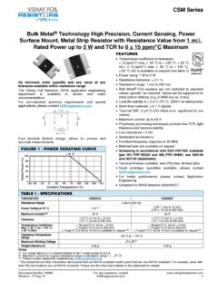
1 Bulk Metal Technology high Precision, Current Sensing, Power Surface Mount, Metal Strip Resistor with Improved Stability %, Resistance Value from 10 m , Rated Power to 1 W and TCR to 0 15 ppm/ C Document Number: 63145 For any questions, contact : CSM s series of low value Current sense resistors provides power and precision in a four terminal, surface mount configuration. Its all welded construction is made up of a Bulk Metal resistive element with plated copper Foil Resistors application engineering department is available to advise and make non-standard technical requirements and special applications, please contact IDV=~ BCFEATURES Temperature coefficient of resistance (TCR): (- 55 C to + 125 C, + 25 C ref.)
2 15 ppm/ C maximum 10 ppm/ C maximum on special request Load life stability to % (70 C, 2000 h at rated power) Power rating: 1 W Resistance tolerance: % Resistance range: 10 m to 100 m Vishay Foil resistors are not restricted to standard values, we can supply specific as required values at no extra cost or delivery ( m vs. 10 m ) Short time overload: % typical Thermal EMF: < 3 V/ C Maximum Current : up to 10 A Surface mount configuration Four terminal (Kelvin) design: allows for precision accurate measurements Terminal finishes available: lead (Pb)-free, tin/lead alloy Screening in accordance with EEE-INST002 available (Per MIL-PRF-55342 and MIL-PRF-49465; see datasheets of 303144 and 303145 ) Prototype quantities available in just 5 working days or sooner.
3 For more information, please contact For better performances please contact Application EngineeringFIGURE 1 - POWER DERATING CURVE- 65 - 50- 250255075100125150170 Ambient Temperature ( C) 100806040200 Rated Power (%)+ 70 CTABLE 1 - PERFORMANCE SPECIFICATIONSPARAMETERCSM2512 SResistance Range10 m to 100 m Power Rating at 70 C1 WMaximum Current10 AMaximum Working Voltage(P x R)1/2 Tightest Tolerance %Temperature Coefficient Maximum (- 55 C to + 125 C, + 25 C ref.) 15 ppm/ C, 10 ppm/ C is availableOperating Temperature Range- 65 C to + 170 CWeight (maximum) g* Pb containing terminations are RoHS compliant, exemptions may apply any questions, contact Document Number: 4-Mar-15 CSM2512 SABOUT CSM (Low Ohm Value 10 m to 100 m )The CSM2512S series of low value Current sense resistors provides power and precision in a four terminal, surface mount configuration.
4 Its all welded construction is made up of a Bulk Metal resistive element with plated copper terminations. For low value resistors in precision applications it is necessary to use four-terminal Kelvin connections to obtain a precise voltage drop across the resistive element. In these applications, the contact resistance and the terminal resistance may have the same order of magnitude or be even greater than that of the element resistance itself. Thus, significant error is introduced because the high temperature coefficient of resistance of the leads and the contact resistance are unavoidably incorporated into the measurements when the Current sense resistor has only two the ability to measure low values to tolerances of or tighter is a concern to both the manufacturer and the user, many situations require coordination of measurement standards between both parties.
5 Coordination is often accomplished by exchange of serialized units with recorded readings to align measurement practices and specific reference standards. The problem is compounded when high -precision Current sensors under moderate to high power experience self-heating (Joule effect) which causes the in-service resistance value to be different from that obtained using low Current measurement equipment. Therefore, the measurement conditions must be defined and accepted at the time of spec preparation-that is, resistance value as determined by specified Current and measured IR-drop following a specified period of equipment is available from a number of sources with varying stated accuracies.
6 Traditional passive Current sensors and shunts generate heat under power, which changes their resistance, and thus their voltage output. The CSM s low absolute TCR reduces errors due to temperature gradients, thus reducing a major source of uncertainty in Current measurement. The CSM can withstand unconventional environmental conditions, including the extremely high temperatures and radiation-rich environments of down-hole oil exploration and well logging, or the deep-sea underwater repeaters in cross-ocean communications. The stability of the CSM can be further enhanced by post-manufacturing operations (PMO), such as temperature cycling, short-time overload, and accelerated load life which are uniquely applicable to Bulk Metal Foil resistors.
7 The device features a low thermal electromotive force (EMF) that is critical in many precision applications. Thermal EMF in DC applications induces a voltage offset in the resistor that is equivalent to adding a small battery into the CSM s all-welded construction is a Bulk Metal resistive element with welded copper terminations, plated for soldering. The terminations make a true continuous contact with the resistive layer along the entire side of the resistive element, thereby minimizing temperature variations. Also, the resistor element is designed to uniformly dissipate power without creating hot spots, and the welded terminations material is compatible with the element material. These design factors result in a very low thermal-EMF(<3 V/ C) resistor, because in addition to the low thermal EMF compatibility of the metals, the uniformity and thermal efficiency of the design minimizes the temperature differential across the resistor, thereby assuring low thermal EMF generation at the leads.
8 This further reduces the battery effect exhibited by most Current -sensing or voltage-reference resistors. Thus, the parasitic voltage generated at the junction of two dissimilar metals, which is especially important in low-value Current -sensing resistors, is minimized, while the pure Current -to-voltage conversion is protected from such interference in DC applications. The stability problems associated with analog circuits are very pervasive, but knowledgeable selection of a few high -quality resistors, networks, or trimming potentiometers in critical locations can greatly improve circuit performance, long-term application-related performance, as well as the designer s peace-of-mind.
9 Additionally, the overall system cost is often reduced when a knowledgeable designer concentrates costs in a few exceptionally stable components with minimal deviation and whose load and environmental stability can often eliminate the necessity of additional compensating circuitry or temperature-controlling systems. The higher reliability and better overall system performances also achieve excellent product results in the field, enhancing market acceptance and product reputation. Designers often unnecessarily pay for tighter tolerances than required simply to accommodate the resistance stability shifts they know to be imminent in an application due to the large application-related changes in the components they selected.
10 Selection of a high -stability component like the CSM in these applications eliminates the need for shift allowance due to planned instability and allows the use of looser initial tolerances than would otherwise be necessary. FIGURE 2 - DIMENSIONS AND IMPRINTING in inches (millimeters)CSM2512S DIMENSIONSHAWBTL(1)CSM2512S LAND PATTERNK elvin ConnectionI1, I2 - CurrentE1, E2 - SenseeIadcbE1E2I1I2 DIMENSIONS - TOLERANCES ( ), * ( )RESISTANCE RANGE ( ) to ( ) ( ) ( ) ( ) ( )* ( )*LAND PATTERN DIMENSIONS - TOLERANCES ( )RESISTANCE RANGE ( ) to ( ) ( ) ( ) ( ) ( ) ( ) Document Number: 63145 For any questions, contact : dots indicate top side of part for mounting purposesTABLE 2 - CSM2512S PERFORMANCE SPECIFICATIONSTESTCONDITIONSMIL-PRF-4946 5B R LIMITSTYPICAL R LIMITSMAXIMUM R LIMITST hermal Shock- 55 C to + 150 C, 1000 cycles, 15 min at each extreme ( % + ) % %Load Life Stability2000 h, 70 C at rated power ( % + ) % %Bias Humidity85 C, 85 % humidity10 % bias, 1000 h ( % + ) % %Short Time Overload5 x rated power for 5 s ( % + ) % % high Temperature Exposure1000 h, 170 C ( % + ) % %Low Temperature StorageMIL-PRF-49465 ( % + ) % %Moisture resistanceMIL-STD-202, method 106, 0 % power,7a and 7b not required ( % + ) % %Shock100 g, 6 ms ( % + ) % %Vibration(10 Hz to 2000 Hz) 20 g ( % + )