Transcription of CAN Reference Guide - TI.com
1 CAN Reference Guide Industrial and Factory Automation Motion Control Transportation Sensors Backplanes 1 CAN Reference Guide texas instruments 2012 Whether you are looking for 5V CAN, CAN, isolated CAN, automotive CAN or industrial CAN, texas instru -ments provides what you need. TI is committed to solving specialized networking requirements while optimizing Various higher level buses and higher level communication protocols have been implemented using or deriving from CAN protocol and physical layer standards. These standards include:ARNIC825: CAN-based communication standard for airborne systems used by current and future aircraft.
2 Driven by Airbus, Boeing and partners. : Communication protocol on top of CAN designed for aerospace. Kingdom: Communication protocol on top of CAN designed as (EN 50325-4): CAN-based, higher-layer protocol for embedded control system. : Industrial network system based on CAN. : Road vehicles. : Tractors and machinery for agriculture and forestry - serial control and communications data network. 2000: National Marine Electronics Association serial network utilizing CAN. : Recommended practice for a serial control & communications vehicle network. : High-speed CAN (HSC) for vehicle applications.
3 P: Protocol on top of CAN designed for fieldbus to SIL 3. CAN transceivers Turbo CAN Programmable slew rate EMC and speed optimized Low-power modes Wake-up via CAN network traffic Protection features Level shifting and compatible Small VSON package Loopback for autobaud Standardized CAN Data Bus/Protocol: ARINC 825, CANaerospace, CAN Kingdom, CANopen, DeviceNet, ISO11783, NMEA2000, SAEJ1939, SAEJ2284, SafetyBUS CAN transceivers Voltage rail and regulator simplification (no 5V required) Power savings vs. 5V Programmable slew rate Low-power modes Protection features Loopback for autobaud & diagnostic purposesIsolated CAN transceivers Isolation up to 5000 VRMS Failsafe outputs I/O 25-year life at rated working voltage CAN physical layers (transceivers) for various applications, microprocessors and power supply systems.
4 Come explore the world of CAN in a wide range of packages and temperatures. These devices are compatible to the ISO11898 2 CAN Reference GuideIntroduction to CAN (Controller Area Network)CAN standard including the original ISO11898:1993 and the updated transceiver part 2 (ISO11898-2, CAN high-speed medium access unit) and part 5 (ISO11898-5, CAN high-speed medium access unit with low-power mode), depending on the application. CAN Applications Automotive (-Q1 versions) Industrial automation Building automation Process control equipment Elevators & lifts Backplane communication Construction equipment Farm equipment Transportation Factory automation Networked sensors & actuators Motor & motion control Medical Telecom Robotics Low power & battery applications CAN-Based Buses and Protocols 2 CAN Reference Guide texas instruments 2012 CAN Reference GuideCAN PHY Basics (ISO11898-2 & -5)
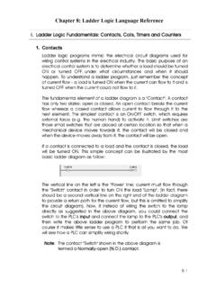
5 3 HS CAN Bus Topology High-Speed Medium Access Unit = HS CAN Transceiver with Transmission Rates of up to 1 Mbit/sHS CAN is a Differential Bus (CANH & CANL Lines) with Two States:Recessive: Logic H Vdiff < = CANH and CANL weakly biased to VCC/2 Dominant: Logic L Vdiff = > CANH and CANL driven differentially by PHY driver Dominant overwrites recessive (enables CAN arbitration to work)Vdiff (D)Vdiff (R)1234 DominantLogic LRecessiveLogic HCAN HCAN LTime, tRecessiveLogic HISO11898 defined CAN as a linear bus topology. The original standard defined the electrical characteristics of a 30node, 40m bus capable of 1mbps.
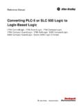
6 This basic topology is easily modified to support various configurations through the use of tradeoffs in data rate, number of nodes and bus length. Node 1 MCU or DSPCANT ransceiverNode 2 MCU or DSPCANT ransceiverNode 3 MCU or DSPCANT ransceiverNode n(with termination)MCU or DSPCANT ransceiverRTERMCANC ontrollerCANC ontrollerCANC ontrollerCANC ontrollerRTERMS implified Receiver & Recessive Biasing DiagramRecessiveRXDVCC/2 CANHCANLR ecessive levelbias generationSimplified Driver DiagramDominantVCCC A N HC A N LTXD 3 CAN Reference Guide texas instruments 2012 CAN Reference GuideTI CAN Transceiver Portfolio4 DeviceI/O and VCC Levels (V)Short-Circuit Protection (V)HBM ESD Protection (kV)Suppy Current, Typical (mA)
7 Standby/Sleep Current, Typical ( A) 4 to +161610370 Standby (Low Power) 4 to + (Ultra Low Power) 4 to +161610 36 to +36166200 Standby (Low Power), Diagnostic 36 to +36166200 (Low Power), Sleep (Ultra Low Power) 36 to +36166200 Standby (Low Power), Autobaud Loop-BackSOIC-8SN65 HVD2515 36 to +361414<275 Standby (Low Power)SOIC-8, PDIP-8SN55 HVD2515 36 to +361414<275 Small Package, High Tempertaure Range ( 55 C to 125 C)SON-8SN65 HVD10405 27 to +401265 Standby (Ultra Low Power with Bus Wake-Up), TXD Dominant Time OutSOIC-8SN65 HVD10505 27 to +4086 NAListen Only Mode, TXD Dominant Time OutSOIC-8SN65 HVD2525 27 to +401213 NADeviceNet CAN, with VREFSOIC-8SN65 HVD2535 27 to +401213 NADeviceNet CAN, LoopbackSOIC-8SN65 HVD2555 27 to +401210NA"Turbo" CAN, "Ideal Passive", TXD Dominant Time Out (<10kbps) 27 to +401210NA"Turbo" CAN, "Ideal Passive", TXD Dominant Time Out (<10kbps), VRXD Level ShiftSOIC-8SN65 HVD2575 27 to +401210NA"Turbo" CAN, "Ideal Passive", TXD Dominant Time Out (<10kbps)
8 , RXD Dominant Time Out, Fault outputSOIC-8 ISO10505 27 to + CAN ( and 5 KVRMS)SOP-8, SOIC-16 Selection Table SN65 HVD230 -4/+16V, -40/85C, D, STB, SC, VREFCANISOLATEDCANS / STB / SLP = Operating Modes: S=Silent, STB = Low Power StandbyMode w/Bus Wake (RXD active), SLP = Low Power Sleep ModeSC = Driver Slope ControlLBK / AB = Loopback Modes: LBK = Diagnostic, AB = AutobaudTDTO = TXD Dominant Time OutLS = Level Shifting RXD pin for P I/OTurbo = Optimized Loop Times for Industrial Networks & CAN Timing MarginMT = Multi-Topology CANDN = Optimized for DeviceNetEMC = Optimized for Lowest EmissionsVREF = Vcc/2 VREF or SPLIT OutputD / P / DRJ / DW / DUB = PackageSN65 HVD231 -4/+16V, -40/85C, D, SLP, SC, VREFSN65 HVD232 -4/+16V, -40/85C, DSN65 HVD233 36V, -40/125C, D,LBK, STB, SC, VREFSN65 HVD234 36V, -40/125C, D, STB, SLP, SC, VREFSN65 HVD235 36V, -40/125C, D,AB, STB, SC, VREFSN65 HVD251 36V.
9 -40/125C, D / P,STB, SC, VREFSN55 HVD251 36V, -55/125C, DRJ, STB, SC, VREFSN65 HVD1050 -27/+40V, -40/125C, D,S, TDTO, VREF, EMCSN65 HVD1040 -27/+40V, -40/125C, D,STB, TDTO, VREF, EMCSN65 HVD257 -27/+40V, -40/125C, D, S, TDTO, MT, TurboSN65 HVD255 -27/+40V, -40/125C, D,S, TDTO, TurboSN65 HVD256 -27/+40V, -40/125C, D,S, TDTO, LS, TurboISO1050 -27/+40V, -55/105C, DW / DUB, TDTO, ISO: 5 k / kV RMS SN65 HVD252 -27/+40V, -40/125C, D,S, VREF, DNSN65 HVD253 -27/+40V, -40/125C, D,S, AB, CANT ransceivers5V CANT ransceiversEXISTINGNEWPREVIEWNew products are listed in bold red.
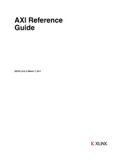
10 Preview products are listed in bold blue. 4 CAN Reference Guide texas instruments 20125 CAN Reference Guide5V Typical Applications5V System with 1050 Type TransceiverNormal and Silent System with HVD230 TransceiverNormal and Standby Modes5V System with 1040 Type TransceiverNormal and Low Power Standby (with CAN Wake) I/O MCU with 5V HVD256 TransceiverNormal and Silent ModesOptimized 5V System with no CAN Wake No extra components. Lower cost VREG (systems normally powered so no low power mode or low IQ requirements). Silent (receive only) mode for software diagnostics on CAN bus.