Transcription of Capacity of Steel Boxes and Covers
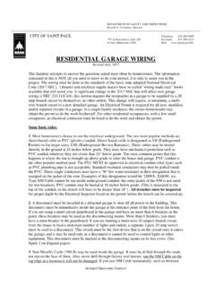
1 Number of Conductors in outlet , Device, and Junction Boxes , and conduit Bodies. Boxes and conduit bodies shall be of sufficient size to provide free space for all enclosed conductors. In no case shall the volume of the box, as calculated in (A), be less than the fill calculation as calculated in (B). The minimum volume for conduit bodies shall be as calculated in (C).The provisions of this section shall not apply to terminal housings supplied with motors. FPN: For volume requirements of motor terminal housings, see and conduit bodies enclosing conductors 4 AWG or larger shall also comply with the provisions of (A) Box Volume Calculations.
2 The volume of a wiring enclosure (box) shall be the total volume of the assembled sections and, where used, the space provided by plaster rings, domed Covers , extension rings, and so forth, that are marked with their volume or are made from Boxes the dimensions of which are listed in Table (A).(1) Standard Boxes . The volumes of standard Boxes that are not marked with their volume shall be as given in Table (A).(2) Other Boxes . Boxes 1650 cm3 (100 ) or less, other than those described in Table (A), and Nonmetallic Boxes shall be durably and legibly marked by the manufacturer with their volume.
3 Boxes described in Table (A) that have a volume larger than is designated in the table shall be permitted to have their volume marked as required by this (A) Metal Boxes (B) Box Fill Calculations. The volumes in paragraphs (B)(1) through (B)(5), as applicable, shall be added together. No allowance shall be required for small fittings such as locknuts and bushings.(1) Conductor Fill. Each conductor that originates outside the box and terminates or is spliced within the box shall be counted once, and each conductor that passes through the box without splice or termination shall be counted once.
4 A looped, unbroken conductor not less than twice the minimum length required for free conductors in shall be counted twice. The conductor fill shall be calculated using Table (B). A con-ductor, no part of which leaves the box, shall not be : An equipment grounding conductor or conductors or not over four fixture wires smaller than 14 AWG, or both, shall be permitted to be omitted from the calcula-tions where they enter a box from a domed luminaire (fixture) or similar canopy and terminate within that box.(2) Clamp Fill. Where one or more internal cable clamps, whether factory or field supplied, are present in the box, a single volume allowance in accor-dance with Table (B) shall be made based on the largest conductor present in the box.
5 No allowance shall be required for a cable connector with its clamping mechanism outside the box.(3) Support Fittings Fill. Where one or more luminaire (fixture) studs or hickeys are present in the box, a single volume allowance in accordance with Table (B) shall be made for each type of fitting based on the largest conductor present in the box.(4) Device or Equipment Fill. For each yoke or strap containing one or more devices or equipment, a double volume allowance in accordance with Table (B) shall be made for each yoke or strap based on the largest conductor connected to a device(s) or equipment supported by that yoke or (B) Volume Allowance Required per Conductor(5) Equipment Grounding Conductor Fill.
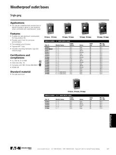
6 Where one or more equipment grounding conductors or equipment bonding jumpers enter a box, a single volume allowance in accordance with Table (B) shall be made based on the largest equipment grounding conductor or equipment bonding jumper present in the box. Where an additional set of equipment grounding conductors, as permitted by (D), is present in the box, an additional volume allowance shall be made based on the largest equip-ment grounding conductor in the additional Receptacles in Damp or Wet Locations.(B) Wet Locations. (1) 15- and 20-Ampere Receptacles in a Wet Location.
7 15- and 20-Ampere, 125- and 250-Volt receptacles installed in a wet location shall have an enclosure that is weatherproof whether or not the attachment plug cap is inserted.(2) Other Receptacles. All other receptacles installed in a wet location shall comply with (B)(2)(a) or (B)(2)(b). (a) A receptacle installed in a wet location, where the product intended to be plugged into it is not attended while in use, shall have an enclosure that is weatherproof with the attachment plug cap inserted or removed.(b) A receptacle installed in a wet location where the product intended to be plugged into it will be attended while in use ( , portable tools) shall have an enclosure that is weatherproof when the attachment plug is removed.
8 *Where no volume allowances are required by (B)(2) through (B)(5).Reproduced with permission NFPA. All National Electrical Code references are from the 2008 Trade SizeMinimum Volume Maximum Number of Conductors* 10 86100x32(4x1 ) (4x1 ) 876653100x54(4x2) 12 109874100x32(4x1 ) 1098763100x38(4x1 ) 12 109874100x54(4x2) 17 15 13 12 10 6120x32(4x1 ) 14 12 11 1085120x38(4x1 ) 16 14 13 1195120x54(4x2) 24 21 18 16 14 875x50x38(3x2x1 ) (3x2x2) (3x2x2 ) (3x2x2 ) (3x2x2 ) (3x2x3 ) 1098763100x54x38 (4x2x1 ) (4x2x1) (4x2x2) (3 x2x2 )masonry (3 x2x3 )
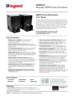
9 Masonry 12 109874min. depthFS - single cover/ gang (1 ) depthFD - single cover/ gang (2) 1098763min. depthFS - multi. cover/ gang (1 ) 1098763min. depthFD - multi. cover/ gang (2) 13 12 10984 Free Space Within Box for Each ConductorSize of Conductor (AWG) ProductsCommerCial ProduCts: switCh and outlet Boxes and CoversVisit our website at or contact us at (800) 621-1506. September 20101479 Capacity of Steel Boxes and CoversMaterial/Finish A ISI/SAE 1008 Pre-galvanized G60, oz/sq ft1 Thickness: minimumConcentric and Eccentric Knockouts B oxes with concentric or eccentric knockouts are suitable for bonding without any additional bonding means where used in circuits above or below 250 V.
10 Unless otherwise noted all concentric or eccentric knockouts are 1/2 3/4 in Fire-Rated Assemblies S ingle and double gang metallic outlet and switch Boxes are acceptable for use in two-hour fire rated walls. For additional information refer to the UL guide card information for metallic outlet Boxes , Raised Ground Boss Groundskeeper raised ground feature on boss inside box provides one or two #10-32 tapped hole, allowing a 3/8 long green ground screw to be threaded into box without contacting mounting surface. Other Boxes provided with flat ground tapped hole, except Plenum Boxes .