Transcription of Catalyst 3560-C and 2960-C Getting Started Guide (English)
1 Catalyst 3560-C and 2960-C Switch Getting Started Guide About This Guide Box Contents Running Express Setup Managing the Switch Installing the Switch Connecting to the Switch Ports In Case of Difficulty Obtaining Documentation and Submitting a Service Request Catalyst 3560-C and 2960-C Switch Getting Started Guide OL-23802-02 1. Catalyst 3560-C and 2960-C Switch Getting Started Guide About This Guide This Guide describes how to use Express Setup to initially configure your Catalyst 3560-C and 2960-C switches. It also covers switch management options, basic installation, port and module connection procedures, and troubleshooting. For additional installation and configuration information for the switch, see the Catalyst 3560-C and 2960-C documentation on For system requirements, important notes, limitations, open and resolved bugs, and last-minute documentation updates, see the release notes, also on For translations of the warnings that appear in this publication, see the Regulatory Compliance and Safety Information for the Catalyst 3560-C and 2960-C switches on When using the online publications, see the documents that match the Cisco IOS.
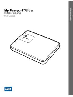
2 Software version running on the switch. Catalyst 3560-C and 2960-C Switch Getting Started Guide 2 OL-23802-02. Catalyst 3560-C and 2960-C Switch Getting Started Guide Box Contents SYST. STAT. DPLX. 1. M ODE SPD 2. 3 SeriesPD. PoE 4. 5. PD 6. CONSOLE 7. 8. POW ER. OVER ETHER. NET. 1. 2. 1. 5 2. P nd 60 Sw ro C -C i a 35. du om a tch ct p nd es D lia 2. oc n 9. um ce 60. en for C. ta th 3. tio e n - 6 4. 7 8. 9. 330856. 10. 1 Catalyst 2960-C switch1 6 Reset button cover 2 Mounting template 7 (Optional) Console cable2. 3 Four rubber mounting feet 8 (Optional) USB cable2. 4 Three number 8 Phillips pan-head screws 9 AC power cord3. 5 Documentation 10 Power adapter4. 1. Catalyst 2960 CPD-8PT-L switch shown for example. Your switch model might look different. 2. Orderable on all Catalyst 2960-C and 3560-C switches. 3.
3 Orderable for switches with an AC power connector. 4. Orderable for switches with an AUX power connector. Catalyst 3560-C and 2960-C Switch Getting Started Guide OL-23802-02 3. Catalyst 3560-C and 2960-C Switch Getting Started Guide Running Express Setup You should use Express Setup to enter the initial IP information. You can then access the switch through the IP address for further configuration. Note To use the CLI-based initial setup program, see Appendix C, Configuring the Switch with the CLI Setup Program, in the switch hardware Guide . You need this equipment: PC with windows 2000, XP, vista , or windows Server 2003. Web browser (Internet Explorer , , or Firefox , , or later) with JavaScript enabled Straight-through or crossover Category 5 or 6 cable Note Before running Express Setup, disable any pop-up blockers or proxy settings on your browser and any wireless client running on your PC.
4 Step 1 Make sure that nothing is connected to the switch. During Express Setup, the switch acts as a DHCP server. If your PC has a static IP address, temporarily configure your PC settings to use DHCP before going to the next step. Note Write down the static IP address. You will need this IP address in Step 10. Step 2 Power the switch: For switch models with an AC power connector Plug the AC power cord into the AC power connector and into an AC power outlet. For switch models with an AUX power connector Connect a 10/100/1000 uplink port to a PoE switch, such as a Catalyst 3750-X. Or Plug the auxiliary power adapter cord into the AUX power connector and into an AC. power outlet. Note For more information on powering the switches, see the Switch Installation chapter in the hardware Guide . Catalyst 3560-C and 2960-C Switch Getting Started Guide 4 OL-23802-02.
5 Catalyst 3560-C and 2960-C Switch Getting Started Guide Step 3 Approximately 30 seconds after the switch powers on, it begins the power-on self-test (POST), which can take up to 5 minutes. During POST, the SYSTEM LED blinks green, and the other LEDs turn green. When POST is complete, the SYSTEM LED turns green, and the other LEDs turn off. Troubleshooting: If the SYSTEM LED blinks green, does not turn green, or turns amber, contact your Cisco representative or reseller. The switch failed the POST. Step 4 Press and hold the Mode button until all of the LEDs next to the console port turn green. You might need to hold the button for 3 to 5. seconds. SYS T. STA T. The switch is now in Express Setup mode. M ODE. D PLX. SPD. PoE. Before going to the next step, make sure that C O NS O. LE. PD. all LEDs next to the console port are green.
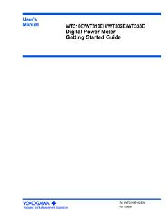
6 Troubleshooting: If the LEDs blink after you press the Mode 208780. button, release it. Blinking LEDs mean that the switch is already configured and cannot go into Express Setup mode. For more information, see the Resetting the Switch . section on page 21. You can also use the CLI. setup program described in the switch hardware Guide . Catalyst 3560-C and 2960-C Switch Getting Started Guide OL-23802-02 5. Catalyst 3560-C and 2960-C Switch Getting Started Guide Step 5 Connect a Category 5 or 6 Ethernet cable to any 10/100 or 10/100/1000 Ethernet downlink port (such as port 1) on the switch front panel. Connect the other end of the cable to the M ODE. SYST. STAT. D PLX. SPD. 1. 2. 3. Ethernet port on your PC. PoE 4 Series 5 PD. PD 6. CO NSO 7. LE 8. PO W ER. O VER ETH. ERN ET. 1. 208787. 2. Before going to the next step, wait until the port LEDs on the switch and your PC or laptop are green or blinking green.
7 The green port LEDs mean a successful connection. Troubleshooting: If the port LEDs do not turn green after about 30 seconds, make sure that: You connected the Ethernet cable to one of the downlink switch ports (not to an uplink port such as the dual-purpose port). You are using an undamaged Category 5. or 6 Ethernet cable. The other device is turned on. Step 6 Enter the IP address in a web browser, and press Enter. When prompted, enter the default password, cisco. Note The switch ignores text in the username field. The Express Setup window appears. Troubleshooting: If the Express Setup window does not appear, make sure that any pop-up blockers or proxy settings on your browser are disabled and that any wireless client is disabled on your PC or laptop. Catalyst 3560-C and 2960-C Switch Getting Started Guide 6 OL-23802-02.
8 Catalyst 3560-C and 2960-C Switch Getting Started Guide Step 7 Enter the required settings in the Express Setup window. Note All entries must be in English letters. Required Fields In the Network Settings fields: In the Management Interface (VLAN ID) field, the default is 1. Note We recommend that you use the default VLAN value. During Express Setup, VLAN 1 is the only VLAN on the switch. Enter a new VLAN ID only if you want to change the management interface through which you manage the switch. The VLAN ID range is 1 to 1001. In the IP Address field, enter the IP address of the switch. In the Subnet Mask field, click the drop-down arrow, and select a subnet mask. In the Default Gateway field, enter the IP address for the default gateway (router). In the Switch Password field, enter your password. The password can be from 1 to 25.
9 Alphanumeric characters, can start with a number, is case sensitive, allows embedded spaces, but does not allow spaces at the beginning or end. In the Confirm Switch Password field, enter your password again. Note You must change the password from the default password, cisco. Additional Fields You can enter the optional information now, or enter it later by using the device manager. For more information about the Express Setup fields, see the online help for the Express Setup window. Click Submit to save your changes and to complete the initial setup. Step 8 After you click Submit, these events occur: The switch is configured and exits Express Setup mode. The browser displays a warning message and tries to connect with the earlier switch IP. address. Typically, connectivity between the PC and the switch is lost because the configured switch IP address is in a different subnet from the IP address on the PC.
10 Step 9 Disconnect the switch from the PC, and install the switch in your network. See the Installing the Switch section on page 12. Catalyst 3560-C and 2960-C Switch Getting Started Guide OL-23802-02 7. Catalyst 3560-C and 2960-C Switch Getting Started Guide Step 10 If you changed the static IP address on your PC in Step 1, change it to the previously configured static IP address. Step 11 You can now manage the switch by using the Cisco Network Assistant, the device manager, or both. See the Managing the Switch section on page 9 for information about configuring and managing the switch. You can display the device manager by following these steps: 1. Start a web browser on your PC or laptop. 2. Enter the switch IP address, username, and password (assigned in Step 7) in the web browser, and press Enter. The device manager page appears.