Transcription of CATIA V5 FEA Tutorials - SDC Publications
1 CATIA V5 FEA Tutorials Releases 12 & 13 Nader G. Zamani University of Windsor SDC Schroff Development Corporation Publications Visit our website to learn more about this and other books: Copyrighted Material Copyrighted Material Copyrighted Material Copyrighted Material CATIA V5 FEA Tutorials 2-1 Chapter 2 Analysis of a Bent Rod with Solid Elements Copyrighted Material Copyrighted Material Copyrighted Material Copyrighted Material 2-2 CATIA V5 FEA Tutorials Clamped endloaded endClamped endloaded endIntroduction In this tutorial, a solid FEA model of a bent rod experiencing a combined load is created.
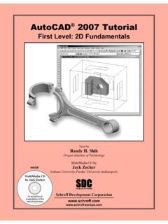
2 No planes of symmetry exist and therefore simplifications cannot be made. Finally, the significance of the von Mises stress in design equation is discussed. 1 Problem Statement The bent rod, shown to the right, is clamped at one end and subjected to a load of 2000 lb as displayed. The steel rod has a Young modulus of 30E+6 psi and Poisson ratio . The nominal dimensions of the rod are also displayed below. Although this problem is more efficiently handled with beam elements, we propose to use solid elements. There are two types of solid elements available in CATIA V5: linear and parabolic. Both are referred to as tetrahedron elements and shown below.
3 The linear tetrahedron elements are faster computationally but less accurate. On the other hand, the parabolic elements require more computational resources but lead to more accurate results. Another important feature of parabolic elements is that they can fit curved surfaces better. In general, the analysis of bulky objects requires the use of solid elements. 2 Creation of the Part in Mechanical Design Solutions Enter the Part Design workbench which can be achieved by different means depending on your CATIA customization. For example, from the standard windows toolbar, select File > New.
4 From the box shown on the right, select Part. This moves you to the part design workbench and creates a part with the default name 5 in 8 in 1 in Cross sectional Radius is 1 in Tetrahedron ElementslinearparabolicTetrahedron ElementslinearparabolicCopyrighted Material Copyrighted Material Copyrighted Material Copyrighted Material Analysis of a Bent Rod with Solid Elements 2-3 In order to change the default name, move the curser to in the tree, right click and select Properties from the menu list. From the Properties box, select the Product tab and in Part Number type wrench. This will be the new part name throughout the chapter.
5 The tree on the top left corner of the screen should look as displayed below. From the tree, select the XY plane and enter the Sketcher . In the Sketcher, draw a circle , and dimension it . In order to change the dimension, double click on the dimension on the screen and in the resulting box enter radius 1. Your simple sketch and the Constraint Definition box used to enter the correct radius are shown below. Leave the Sketcher . From the tree, select the XY plane and enter the Sketcher . Draw the spine of the bent rod by using Profile and dimension it to meet the geometric specs. In the Sketcher, the spine should match the figure below on the right.
6 Upon leaving the Sketcher , the screen and the tree should be as shown below. Copyrighted Material Copyrighted Material Copyrighted Material Copyrighted Material 2-4 CATIA V5 FEA Tutorials You will now use the ribbing operation to extrude the circle along the spine (path). Upon selecting the rib icon , the Rib Definition box opens. Select the circle ( ) and the spine ( ) as indicated. The result is the final part shown below. Regularly save your work. 3 Entering the Analysis Solutions From the standard windows tool bar, select Start > Analysis & Simulation > Generative Structural Analysis There is a second workbench known as the Advanced Meshing Tools which will be discussed later.
7 The first thing one can note is the presence of a Warning box indicating that material is not properly defined on wrench. This is not surprising since material has not yet been assigned. This will be done shortly and therefore you can close this box by pressing OK . A second box shown below, New Analysis Case is also visible. The default choice is Static Analysis which is precisely what we intend to use. Therefore, close the box by clicking on OK . Copyrighted Material Copyrighted Material Copyrighted Material Copyrighted Material Analysis of a Bent Rod with Solid Elements 2-5 Finally, note that the tree structure gets considerably longer.
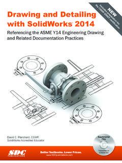
8 The bottom branches of the tree are presently unfilled , and as we proceed in this workbench, assign loads and restraints, the branches gradually get filled . Another point that cannot be missed is the appearance of an icon close to the part that reflects a representative size and sag . This is displayed in the figure below. The concept of element size is self-explanatory. A smaller element size leads to more accurate results at the expense of a larger computation time. The sag terminology is unique to CATIA . In FEA, the geometry of a part is approximated with the elements. The surface of the part and the FEA approximation of a part do not coincide.
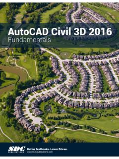
9 The sag parameter controls the deviation between the two. Therefore, a smaller sag value could lead to better results. There is a relationship between these parameters that one does not have to be concerned with at this point. The physical sizes of the representative size and sag on the screen, which also limit the coarseness of the mesh can be changed by the user. There are two ways to change these parameters: The first method is to double click on the representative icons on the screen which forces the OCTREE Tetrahedron Mesh box to open as shown to the right. Change the default values to match the numbers in the box.
10 Notice that the type of the elements used (linear/parabolic) is also set in this box. Select OK. The second method of reaching this box is through the tree. By double clicking on the branch labeled OCTREE Tetrahedron Mesh shown below, the same box opens allowing the user to modify the values. Representative sagRepresentative sizeRepresentative sagRepresentative size Copyrighted Material Copyrighted Material Copyrighted Material Copyrighted Material 2-6 CATIA V5 FEA Tutorials In order to view the generated mesh, you can point the curser to the branch Nodes and Elements, right click and select Mesh Visualization. This step may be slightly different in some UNIX machines.