Transcription of CE 405: Design of Steel Structures – Prof. Dr. A. Varma
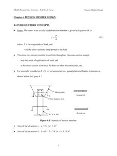
1 CE 405: Design of Steel Structures Prof. Dr. A. Varma CHAPTER 5. BOLTED CONNECTION INTRODUCTORY CONCEPTS There are different types of bolted connections. They can be categorized based on the type of loading. - Tension member connection and splice. It subjects the bolts to forces that tend to shear the shank. - Beam end simple connection. It subjects the bolts to forces that tend to shear the shank. - Hanger connection. The hanger connection puts the bolts in tension 1CE 405: Design of Steel Structures Prof.
2 Dr. A. Varma The bolts are subjected to shear or tension loading. - In most bolted connection, the bolts are subjected to shear. - Bolts can fail in shear or in tension. - You can calculate the shear strength or the tensile strength of a bolt Simple connection: If the line of action of the force acting on the connection passes through the center of gravity of the connection, then each bolt can be assumed to resist an equal share of the load. The strength of the simple connection will be equal to the sum of the strengths of the individual bolts in the connection.
3 We will first concentrate on bolted shear connections. 2CE 405: Design of Steel Structures Prof. Dr. A. Varma BOLTED SHEAR CONNECTIONS We want to Design the bolted shear connections so that the factored Design strength ( Rn) is greater than or equal to the factored load. So, we need to examine the various possible failure modes and calculate the corresponding Design strengths. Possible failure modes are: - Shear failure of the bolts - Failure of member being connected due to fracture or block shear or.
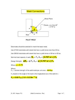
4 - Edge tearing or fracture of the connected plate - Tearing or fracture of the connected plate between two bolt holes - Excessive bearing deformation at the bolt hole Shear failure of bolts - Average shearing stress in the bolt = fv = P/A = P/( db2/4) - P is the load acting on an individual bolt - A is the area of the bolt and db is its diameter - strength of the bolt = P = fv x ( db2/4) where fv = shear yield stress = - Bolts can be in single shear or double shear as shown below. - When the bolt is in double shear, two cross-sections are effective in resisting the load.
5 The bolt in double shear will have the twice the shear strength of a bolt in single shear. 3CE 405: Design of Steel Structures Prof. Dr. A. Varma Failure of connected member - We have covered this in detail in Ch. 2 on tension members - Member can fail due to tension fracture or block shear. Bearing failure of connected/connecting part due to bearing from bolt holes - Hole is slightly larger than the fastener and the fastener is loosely placed in hole - Contact between the fastener and the connected part over approximately half the circumference of the fastener - As such the stress will be highest at the radial contact point (A).
6 However, the average stress can be calculated as the applied force divided by the projected area of contact - Average bearing stress fp = P/(db t), where P is the force applied to the fastener. - The bearing stress state can be complicated by the presence of nearby bolt or edge. The bolt spacing and edge distance will have an effect on the bearing str. - Bearing stress effects are independent of the bolt type because the bearing stress acts on the connected plate not the bolt. 4CE 405: Design of Steel Structures Prof.
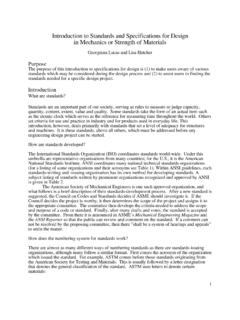
7 Dr. A. Varma - A possible failure mode resulting from excessive bearing close to the edge of the connected element is shear tear-out as shown below. This type of shear tear-out can also occur between two holes in the direction of the bearing load. Rn = 2 x Fu Lc t = Fu Lc t 5CE 405: Design of Steel Structures Prof. Dr. A. Varma - To prevent excessive deformation of the hole, an upper limit is placed on the bearing load. This upper limit is proportional to the fracture stress times the projected bearing area Rn = C x Fu x bearing area = C Fu db t If deformation is not a concern then C = 3, If deformation is a concern then C= C = corresponds to a deformation of in.
8 - Finally, the equation for the bearing strength of a single bolts is Rn where, = and Rn = Lc t Fu < db t FuLc is the clear distance in the load direction, from the edge of the bolt hole to the edge of the adjacent hole or to the edge of the material - This relationship can be simplified as follows: The upper limit will become effective when Lc t Fu = db t Fu , the upper limit will become effective when Lc = 2 db If Lc < 2 db, Rn = Lc t Fu If Lc > 2 db, Rn = db t Fu 6CE 405: Design of Steel Structures Prof.
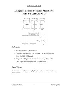
9 Dr. A. Varma Design PROVISIONS FOR BOLTED SHEAR CONNECTIONS In a simple connection, all bolts share the load equally. TTT/nT/nT/nT/nT/nT/nTTT/nT/nT/nT/nT/nT/n In a bolted shear connection, the bolts are subjected to shear and the connecting / connected plates are subjected to bearing stresses. Bolt in shearBearing stresses in plateBearing stresses in plateTTTTBolt in shearBearing stresses in plateBearing stresses in plateBolt in shearBearing stresses in plateBearing stresses in plateTTTT The shear strength of all bolts = shear strength of one bolt x number of bolts The bearing strength of the connecting / connected plates can be calculated using equations given by AISC specifications.
10 The tension strength of the connecting / connected plates can be calculated as discussed earlier in Chapter 2. AISC Design Provisions Chapter J of the AISC Specifications focuses on connections. Section J3 focuses on bolts and threaded parts 7CE 405: Design of Steel Structures Prof. Dr. A. Varma AISC Specification indicates that the minimum distance (s) between the centers of bolt holes is 2bd32. A distance of 3db is preferred. AISC Specification indicates that the minimum edge distance (Le) from the center of the bolt to the edge of the connected part is given in Table on page Table specifies minimum edge distances for sheared edges, edges of rolled shapes, and gas cut edges.