Transcription of Ceiling Microphone Array Installation Manual - Rev.1
1 Ceiling Microphone ArrayINSTALLATION MANUALINTRODUCTION ..1 Product Overview ..1 Device Application ..1 Installation ..2 Physical Characteristics ..2 Microphone Array Dimensions (Excluding Cables and Mounting) ..2 Cables ..2 Pass-through Mounting Assembly ..3 Tools Required ..3 Determining the Placement ..3 Installing the Microphone Array ..4 SOFTWARE SETUP OF THE Ceiling Microphone Array ..7 Converge Pro Microphone Array Setup ..7 Interact Pro Microphone Array Setup ..9 Interact AT Microphone Array Setup ..11 COMPLIANCE ..13 SERVICE AND SUPPORT ..14 Table of Contents1 Technical Support: OVERVIEWThe ClearOne Ceiling Microphone Array enhances any conferencing application which demands high-quality audio.
2 The Ceiling Microphone Array is easily installed and combines affordability with exceptional audio quality. The Ceiling Microphone Array features three microphones that are mounted together into a single unit Array , providing the rich sound of three individual unidirectional microphones while maintaining full 360 degree coverage. The design minimizes noise pickup from sources near the Ceiling and frees table space while maintaining speech quality and APPLICATIONThe Ceiling Microphone Array is ideal for use in medium to large conference rooms, training rooms, court rooms, learning centers, convention centers.
3 Any area needing unobtrusive, quality audio should be done by a qualified Dealer Service Manual 2 InstallationPHYSICAL CHARACTERISTICSM icrophone Array Dimensions (Excluding Cables and Mounting)Length: in ( cm)Diameter: in ( cm)CABLESTwo cables and a mixer adapter are used for connecting from the Microphone Array through the pass-through Mounting Assembly to the mixer. One 4-pin mini-XLR cable is used for connecting the Microphone Array to the pass-through Mounting Assembly. (Both 12-inch and 24-inch 4-pin mini-XLR drop-down cables are provided allowing you to use the most suitable length.)
4 A grommet is included to cover where the cable connects to the pass-through mounting assembly. One 25-foot RJ45 Male to RJ45 Male CAT5e cable is used connecting at the pass-through mounting assembly going to the mixer. If required this cable can be extended to 328Ft (100m) using the 568B wiring standard. One RJ45 Male to mixer adapter is used to connect the RJ45 cable to the mixer. (There are two types depending on which is ordered - one with 3 mini-Phoenix connectors, one with 3 XLR-M connectors.)The Microphone Array is phantom powered by the mixer through the mixer adapter, the RJ45 cable and the 4-pin mini-XLR Technical Support.
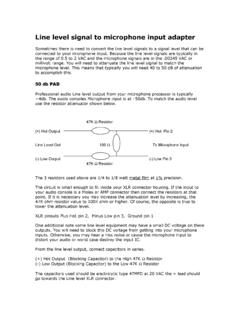
5 MOUNTING ASSEMBLYThis assembly includes a threaded body with integrated mini-XLR and RJ45 connectors, and the required washers and nuts for fastening in a suspended Ceiling REQUIREDYou will need a drill and a 1-inch hole saw bit to install the mounting adapter, and an adjust-able wrench to tighten the adapter THE PLACEMENTD etermine the placement of the Ceiling Microphone Array by the characteristics of the room where it will be installed and the pickup pattern of the Microphone Array . The choice of either the 12 or 24-inch Microphone cable determines how close the Microphone Array is to the users below and how wide the pickup pattern extends.
6 Single and Dual Array pickup patterns and placements are illustrated below: Microphone Array End Includes 4-pin Mini-XLR ConnectorCable to Mixer End Includes Female RJ45 ConnectorSINGLE Microphone Array PICK-UP PATTERN120 from mic Array (Best pick-up)180 from mic Array (Good pick-up)DUAL Microphone Array PICK-UP PATTERN120 from either mic Array (Best pick-up)180 from either mic Array (Good pick-up) Installation Manual 4 INSTALLING THE Microphone ARRAY1. Drop the Ceiling tile where you have selected to install the Microphone Run the 25-ft RJ45 cable from the mixer location into the space above the suspended Ceiling and down through the opening of the removed tile to conceal the Drill a 1-inch hole through each removed Ceiling tile where the pass-through Mounting Assembly will be 1-Inch Hole for Placement of Mounting Assembly4.
7 Insert the Mounting Assembly through the hole with the RJ45 end above the Ceiling tile, then tighten into place with the washers against both faces of the tile followed by the nuts. Be sure to place the washer and nut on the mini-XLR end as close to the end of the threaded assembly as possible to allow the Microphone Array cable and grommet to fit snugly against the Ceiling tile. 5 Technical Support: Ceiling Tile SurfaceAbove Ceiling Tile Surface5. Plug the RJ45 cable into the top end of Mounting Assembly, then lift the Ceiling tile back into place. 6. Make sure the mini-XLR cable is fed through the grommet.
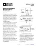
8 Connect the mini-XLR connector into the receiving plug at the bottom of the Mounting Assembly, then slide the Grommet over the cable and connector snugging it over the Mounting Assembly against the Ceiling tile. Mini-XLR Connector below Ceiling Tile SurfaceMini-XLR PlugGrommetRJ45 Connector above Ceiling Tile SurfaceRJ45 PlugINSTALLATION Manual 67. Attach the Microphone Array to the hanging end of the mini-XLR Connect the RJ45 Male to Mixer adapter cable for your mixer: The Converge Pro requires the RJ45 to mini-Phoenix adapter cable.
9 The RJ45 to XLR-M adapter is for the Interact Pro and Interact AT Connect the CAT5e cable from the Ceiling Microphone Array to the adapter cable ordered to match the Microphone inputs on the mixer. Note: There are three connectors that plug into the mixer, one for each of the three microphones in the Array . Mini-Phoenix Adapter for Converge Pro and Interact Pro MixersXLR-M Adapter for the Interact AT MixerCAT5e Cable Inputs7 Technical Support: Setup of the Ceiling Microphone ArrayThe Ceiling Microphone Array can be used with the ClearOne Converge Pro, Interact Pro, and Interact AT audio conferencing mixers. Each Ceiling Microphone Array requires 3 Microphone inputs.
10 Attention Installers: You must apply the software setup and filter settings in the audio conferencing mixer to obtain the best performance from the ClearOne Ceiling Microphone Array . Failure to apply these filter settings will result in degraded audio PRO Microphone Array SETUP1. With Converge Console connect to the Converge Pro. 2. In Converge Console go to the channel view for the first Microphone input. 3. Verify PPWR (Phantom Power) is turned on. The Ceiling Microphone requires phantom power for operation. 4. As a starting point set the Coarse Gain to 50 dB and the Fine Gain to 0 dB.