Transcription of centralized lighting 5000/6000/7000 control …
1 87centralized lighting 5000 / 6000 /7000control system lutron World Headquarters: lighting control system How to Lay Out a SystemDesign TipsGP Dimming Panels are available with Main Lugs, Main Breakers,or Dual-Tap Main separate Power Panel is required for each voltage type (120V, 220-240V, 277V, 230V, 100V) and feed type (Normal or Emergency).Multiple circuits can be controlled per ballasts are required to dim fluorescent more information on lutron Fluorescent Dimming Ballasts, see pg. Panels can be distributed throughout the building to reduce wire than 512 zones requires a multiple processor GRAFIK 7000 7000 should also be selected if graphical control is the project requires up to 128 zones, a GRAFIK 5000 system should be selected;up to 512 zones, a GRAFIK 6000 is appropriate; and a GRAFIK 7000 may be used for applications containing 64 to over 16,000 zones.
2 For example, the second floor requires90 zones and the first floor requires 120 zones. A GRAFIK 6000should be used to accommodate the total number of zones, 210, for this 7000 may be used for any application requiring graphical control , data logging,multiple processors, or control from multiple to the summary of circuits in this example, the second floor has 63 dimming circuits, requiring two 24 circuit Dimming Panels plus one 20 circuit Dimming 47 switched circuits, two 24 circuit Softswitch Panels will accommodate the number of switched circuits for that 1 Board Room441 Room 2 Open Office972(through)Room 31 Open Office863 Room 32 Executive Office422 FloorFloorFloortotal= 90total= 63total = 47 Room 1 Lobby632 Room 2 Cafeteria871 Room 3 Employee Lounge662(through)Room 31 Office422 FloorFloorFloortotal = 120 total =109total = 702ndFloor1stFloorRoom (Area)DescriptionNo.
3 Of Circuits SwitchedNo. of ZonesNo. of Circuits DimmedStep 2 Select Design ElementsIdentify additional control schemes for the project ( DMX integration, TimeScheduling, Wireless control ) and addappropriate control Station Devices toachieve Design Elements available,see pgs. 1 Determine number of zones, circuits, and selectPower PanelsA zone is a group of lights or shades that arealways controlled EyeControls have the ability to dim most popularsources and to control several zones at onetime from one button press. Important factorsto consider when creating zones are flexibilityof control and lighting control system How to Lay Out a System88 For example, use Wallstations in the Board Room and Cafeteria for local lighting occupancy sensors in the Employee Lounge for energy-saving Photosensors in the Lobby for daylight compensation and Graphical control Software to monitor, control , and navigate through the building and control the lighting system from one Support: hours/7 days (US/CAN) To Order.
4 ET (US/CAN) centralized lighting control system How to Lay Out a SystemStep 3 Add Local Controls andControl Interfaces to Implement Design this example, a Four-button Wallstation with Off and Raise/Lower,SO-4SN (see pg. 106), is chosen for the Cafeteria to recall preset light Slider Wallstation, OMXSL-4-3G (see pg. 121), is placed in the Boardroom as a local Contact Closure Interface, OMX-AV (see pg. 124), is required to interface the drycontact closure from the occupancy sensor to the system in the Employee Daylight control , OMX-DACPI-A-WH (see pg. 126), is used to integratePhotosensors in the lobby for daylight compensation and energy Software, pg.
5 97, is used to manage the entire building s lighting system from the Facility Manager s TipsGRAFIK 5000 can accommodate up to 32 control Station 6000 can accommodate up to 96 control Station 7000 can accommodate up to 192 control Station Devices on a single Processor. Up to 32 Processors can be linked to control over 6,000 control Station Station Device functions are configured through software to perform avariety of functions. Make selection of wallstations based on using non-dim circuits to control PerSONNA fixtures for personalworklight control in office areas. Timeclock control over these circuits can stillbe maintained through the centralized lighting control SystemProcessorfor total building lighting eLumen manager should be located in a securable area for setup and operation/monitoring of the Hand-Held Programmer can be used to set preset light levels within a Programming Jacks throughout the project in areas where real-timeprogramming is required.
6 In a GRAFIK 7000 system , the Hand-HeldProgrammer only affects the processor to which it is currently 4 Support the design through one-line diagramsand written product Station Device (CSD) and User Interface (UI) links require lutron all-in-one CableGRX-CBL-46L-500 (5-Conductor) or two #12 (Class 2) plus one Belden #9461 or Alpha#2211 TipComplete product specifications are available at lighting control system How to Lay Out a lutron World Headquarters: lighting control system Overall WiringWindow treatment and lighting zones can be incorporatedinto scenes together in the following three possible combinations: lights and window treatment scenes,lights-only scenes, and window treatment -only pg.
7 103 CSD LinkEthernet Interface Jack, pg. 100 Ethernet Interface, pg. 100 CSD LinkUI LinkPower Panel LinkWindowTreatment Wallstations,pg. 133 ControlInterfaces,pg. 122To device by othersZONE 1 ZONE 2 ZONE 3 ZONE 4 ZONESXXXXXXLast Window OPENINGWest Window STOPPED83%48%34%OFFG5000 PWallstations, pg. 104 Wire Type CWire Type CWire Type CType A(2) #12 AWG wires (120V/277V)Type B(3) #12 AWG wires (120V/277V)Type C(2) #12 AWG Class 2 wires + (1) twisted, shielded pair #18 AWG Class 2 wires (or lutron Model #: GRX-CBL-46L)Type D(3) #16-20 AWG wires (24 VAC, plus earth ground) + (4) twisted, shielded #18 AWG (Available from lutron Model #: SVQ-CBL-250)Type E(3) #18-22 AWG wires (24 VAC, plus earth ground)* Note.
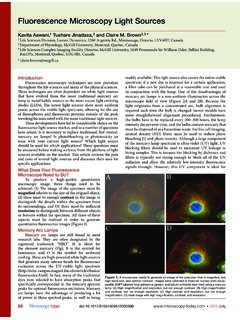
8 Wire to a Sivoia QED plug-in transformer (shown),orjunction box mount transformer,ora Sivoia QEDpower Sivoia QEDtransformer can power only one EDU regardless of window treatment size up to 200 (61m) Type KeyeLumen Managers, pg. 95 centralized lighting control system Overall Wiring90 Processor Panel, pg. 94 Wire Type CTechnical Support: hours/7 days (US/CAN) To Order: ET (US/CAN) centralized lighting control system Overall WiringThe Sivoia QED Controller, which connects to both the Sivoia QEDcommunication link and the control Station Devicelink, is used for programming and operating the group of window treatments wired to the control .
9 Each Sivoia QEDC ontroller occupies one address on the wallstation sensor inputsand timeclock eventscan be used to selectSivoia QED Controllable WindowTreatments QEDLinkSivoia QEDC ontroller, pg. 13324 VACT ransformer*Sivoia QEDC ontrollable Roller ShadesWire Type EWire Type DWire Type APower Panels, pgs. 152-171 Wire Type BLutron Hi-Lumeor Eco-10 (ECO-Series) FluorescentDimming Ballasts, pg. 236 CSIILPM odulesMotor ModulesCustom Combination Power Panel, pg. 172 Motor Modules, which are installed in Custom Combination Power Panels,can be used to control AC motorized window treatments, draperies,or projection screens. Each Motor Module can control up to four 3-wire AC :Only one motor per Motor Module output; motors cannot be paralleled.
10 Multiple Motor Module outputs may be combined into a single zone in the Combination Power Panels can contain a mix of dimming modules and motor modules for 4 to 32 Motorized Roller Shades(one motor permodule output)AC Motorized Projection Screen(one motor per module output)IncandescentLoadsWire Type BWire Type AOne group of SivoiaQEDC ontrollableWindow Treatmentsmoving simultaneouslyacts as a single zone in the lighting control system Overall Wiring91 Wire Type E24 VACT ransformer*Compatible lutron ProductsSPECIFICATIONS Load types:- Controlled through Power Panels, see pg. 146- For more information on neon/cold cathode and 2-circuit track,see Application Notes, pgs.