Transcription of Chapter 15 Transformer Design
1 Fundamentals of Power ElectronicsChapter 15: Transformer design1 Chapter 15 Transformer DesignSome more advanced Design issues, not considered in previouschapter: Inclusion of core loss Selection of operating fluxdensity to optimize total loss Multiple winding Design : as inthe coupled-inductor case,allocate the available windowarea among several windings A Transformer designprocedure How switching frequencyaffects Transformer sizen1 : n2: nkR1R2Rk+v1(t) +v2(t) +vk(t) i1(t)i2(t)ik(t)Fundamentals of Power ElectronicsChapter 15: Transformer design2 Chapter 15 Transformer Transformer Design : Basic A step-by-step Transformer Design AC inductor SummaryFundamentals of Power ElectronicsChapter 15: Transformer Transformer Design :Basic ConstraintsCore lossTypical value of for ferrite materials: or B is the peak value of the ac component of B(t), , the peak ac fluxdensitySo increasing B causes core loss to increase rapidlyThis is the first constraintPfe=Kfe( B) AclmFundamentals of Power ElectronicsChapter 15: Transformer design4 Flux densityConstraint #2 Flux density B(t) is related to theapplied winding voltage accordingto Faraday s Law.
2 Denote the volt-seconds applied to the primarywinding during the positive portionof v1(t) as 1: 1=v1(t)dtt1t2 This causes the flux to change fromits negative peak to its positive Faraday s law, the peak valueof the ac component of flux density isTo attain a given flux density,the primary turns should bechosen according toarea 1v1(t)t1t2t B= 12n1 Acn1= 12 BAcFundamentals of Power ElectronicsChapter 15: Transformer design5 Copper lossConstraint #3 Allocate window area between windings in optimum manner, asdescribed in previous section Total copper loss is then equal toPcu= (MLT)n12 Itot2 WAKuItot=njn1Ij j=1kwithEliminate n1, using result of previous slide:Note that copper loss decreases rapidly as B is increasedPcu= 12 Itot24Ku(MLT)WAAc21 B2 Fundamentals of Power ElectronicsChapter 15: Transformer design6 Total power loss4.
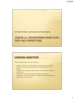
3 Ptot = Pcu + PfePtot=Pfe+PcuThere is a value of Bthat minimizes the totalpower lossPcu= 12 Itot24Ku(MLT)WAAc21 B2 Pfe=Kfe( B) Aclm BPowerlossPtotCopper loss PcuCore loss PfeOptimum BFundamentals of Power ElectronicsChapter 15: Transformer design75. Find optimum flux density BPtot=Pfe+PcuGiven thatThen, at the B that minimizes Ptot, we can writeNote: optimum does not necessarily occur where Pfe = Pcu. Rather, itoccurs wheredPtotd( B)=dPfed( B)+dPcud( B)=0dPfed( B)= dPcud( B)Fundamentals of Power ElectronicsChapter 15: Transformer design8 Take derivatives of core and copper lossNow, substitute intoand solve for B:Optimum B for agiven core andapplicationPcu= 12 Itot24Ku(MLT)WAAc21 B2 Pfe=Kfe( B) AclmdPfed( B)= Kfe( B) 1 AclmdPcud( B)= 2 12 Itot24Ku(MLT)WAAc2( B) 3dPfed( B)= dPcud( B) B= 12 Itot22Ku(MLT)WAAc3lm1 Kfe1 +2 Fundamentals of Power ElectronicsChapter 15: Transformer design9 Total lossSubstitute optimum B into expressions for Pcu and Pfe.
4 The total loss is:Rearrange as follows:Left side: terms depend on coregeometryRight side: terms depend onspecifications of the applicationPtot=AclmKfe2 +2 12 Itot24Ku(MLT)WAAc2 +2 2 +2+ 22 +2 WAAc2( 1)/ (MLT)lm2/ 2 +2+ 22 +2 +2 = 12 Itot2 Kfe2/ 4 KuPtot +2/ Fundamentals of Power ElectronicsChapter 15: Transformer design10 The core geometrical constant KgfeDefineDesign procedure: select a core that satisfiesAppendix D lists the values of Kgfe for common ferrite coresKgfe is similar to the Kg geometrical constant used in Chapter 14: Kg is used when Bmax is specified Kgfe is used when B is to be chosen to minimize total lossKgfe=WAAc2( 1)/ (MLT)lm2/ 2 +2+ 22 +2 +2 Kgfe 12 Itot2 Kfe2/ 4 KuPtot +2/ Fundamentals of Power ElectronicsChapter 15: Transformer Step-by-steptransformer Design procedureThe following quantities are specified, using the units noted:Wire effective resistivity ( -cm)Total rms winding current, ref to priItot(A)Desired turns ratiosn2/n1, n3/n1, pri volt-sec 1(V-sec)Allowed total power dissipationPtot(W)Winding fill factorKuCore loss exponent Core loss coefficient Kfe(W/cm3T )Other quantities and their dimensions:Core cross-sectional areaAc(cm2)Core window areaWA(cm2)Mean length per turnMLT(cm)Magnetic path length le (cm)Wire areas Aw1.
5 (cm2)Peak ac flux density B (T)Fundamentals of Power ElectronicsChapter 15: Transformer core sizeSelect a core from Appendix D that satisfies this may be possible to reduce the core size by choosing a core materialthat has lower loss, , lower 12 Itot2 Kfe2/ 4 KuPtot +2/ 108 Fundamentals of Power ElectronicsChapter 15: Transformer peak ac flux densityAt this point, one should check whether the saturation flux density isexceeded. If the core operates with a flux dc bias Bdc, then B + Bdcshould be less than the saturation flux density the core will saturate, then there are two choices: Specify B using the Kg method of Chapter 14, or Choose a core material having greater core loss, then repeatsteps 1 and 2 B=108 12 Itot22Ku(MLT)WAAc3lm1 Kfe1 +2 Fundamentals of Power ElectronicsChapter 15: Transformer design143.
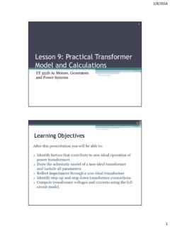
6 And turnsPrimary turns:Choose secondary turns according todesired turns ratios:n2=n1n2n1n3=n1n3n1n1= 12 BAc104 Fundamentals of Power ElectronicsChapter 15: Transformer design155. and wire sizes 1=n1I1n1 Itot 2=n2I2n1 Itot k=nkIkn1 ItotFraction of window areaassigned to each winding:Choose wire sizes accordingto:Aw1 1 KuWAn1Aw2 2 KuWAn2 Fundamentals of Power ElectronicsChapter 15: Transformer design16 Check: computed Transformer modeliM,pk= 12 LMR1= n1(MLT)Aw1R2= n2(MLT)Aw2 Predicted magnetizinginductance, referred to primary:Peak magnetizing current:Predicted winding resistances:n1 : n2: nkR1R2 Rki1(t)i2(t)ik(t)LMiM(t)LM= n12 AclmFundamentals of Power ElectronicsChapter 15: Transformer 1: Single-output isolatedCuk converter100 W fs = 200 kHzD = = 5Ku = Ptot = WUse a ferrite pot core, with Magnetics Inc.
7 P material. Lossparameters at 200 kHz areKfe = = + +V5 V Vg25 Vn : 1I20 AIg4 A+v2(t) v1(t)+i1(t)i2(t) vC2(t) ++ vC1(t) Fundamentals of Power ElectronicsChapter 15: Transformer design18 Waveformsv1(t)i1(t)i2(t)DTsArea 1VC1 nVC2D'TsI/n IgI nIgApplied primary volt-seconds: 1=DTsVc1=( ) (5 sec ) (25 V)= V secApplied primary rmscurrent:I1=DIn2+D'Ig2=4 AApplied secondary rmscurrent:I2=nI1=20 ATotal rms windingcurrent:Itot=I1+1nI2=8 AFundamentals of Power ElectronicsChapter 15: Transformer design19 Choose core sizeKgfe ( 10 6)( 10 6)2(8)2( )2 ( ) ( ) core data of Appendix D lists 2213 pot core withKgfe = smaller pot core is not large of Power ElectronicsChapter 15: Transformer design20 Evaluate peak ac flux densityThis is much less than the saturation flux density of T.
8 Values of B in the vicinity of T are typical for ferritedesigns that operate at frequencies in the vicinity of 100 kHz. B=108( 10 6)( 10 6)2(8)22( )( )( )( )3( )1( )( )1 TeslaFundamentals of Power ElectronicsChapter 15: Transformer design21 Evaluate turnsn1=104( 10 6)2( )( )= turnsn2=n1n= turnsIn practice, we might selectn1 = 5and n2 = 1 This would lead to a slightly higher flux density and slightly of Power ElectronicsChapter 15: Transformer design22 Determine wire sizesFraction of window area allocated to each winding: 1=4A8A= 2=1520 A8A= (Since, in this example, the ratio ofwinding rms currents is equal to theturns ratio, equal areas areallocated to each winding)Wire areas:Aw1=( )( )( )(5)= 10 3cm2Aw2=( )( )( )(1)= 10 3cm2 From wire table,Appendix D:AWG #16 AWG #9 Fundamentals of Power ElectronicsChapter 15: Transformer design23 Wire sizes.
9 DiscussionPrimary5 turns #16 AWGS econdary1 turn #9 AWG Very large conductors! One turn of #9 AWG is not a practical solutionSome alternatives Use foil windings Use Litz wire or parallel strands of wireFundamentals of Power ElectronicsChapter 15: Transformer design24 Effect of switching frequency on Transformer sizefor this P-material Cuk converter frequencyBmax , TeslaPot core size4226362226162213181118112213261625 kHz50 kHz100 kHz200 kHz250 kHz400 kHz500 kHz1000 kHz As switching frequency isincreased from 25 kHz to250 kHz, core size isdramatically reduced As switching frequency isincreased from 400 kHz to1 MHz, core sizeincreasesFundamentals of Power ElectronicsChapter 15: Transformer 2 Multiple-Output Full-Bridge Buck ConverterSwitching frequency150 kHzTransformer frequency75 kHzTurns ratio110:5.
10 15 Optimize Transformer atD = : n2+v1(t) + D1Q1D2Q2D3Q3D4Q4i1(t)+5 V D5D6I5V100 Ai2a(t)+15 V D7D8i3a(t)n1 :: n2: n3: n3i2b(t)i2b(t)I15V15 AT1Vg160 VFundamentals of Power ElectronicsChapter 15: Transformer design26 Other Transformer Design detailsUse Magnetics, Inc. ferrite P material. Loss parameters at 75 kHz:Kfe = W/T cm3 = E-E core shapeAssume fill factor ofKu = (reduced fill factor accounts for added insulation requiredin multiple-output off-line application)Allow Transformer total power loss ofPtot = 4 W(approximately of total output power)Use copper wire, with = 10 6 -cmFundamentals of Power ElectronicsChapter 15: Transformer design27 Applied Transformer waveformsti2a(t)0i3a(t)0 DTsTs2 TsTs+DTsi1(t)0v1(t)00Vg VgArea 1= VgDTsn2n1I5V+n3n1I15V n2n1I5V+ : n2+v1(t) D3D4i1(t)D5D6i2a(t)D7D8i3a(t)n1 :: n2: n3: n3i2b(t)i2b(t)T1 Fundamentals of Power ElectronicsChapter 15.