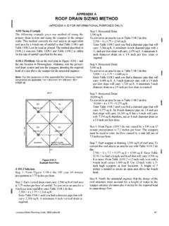
Transcription of CHAPTER 16 STRUCTURAL DESIGN - eCodes
1 CHAPTER 16 STRUCTURAL DESIGNSECTION provisions of this CHAPTER shall govern thestructural DESIGN of buildings, structures and portions thereofregulated by this :Buildings and structures located within thehigh-velocity hurricane zone shall comply with the provi-sions of Sections 1615 through 1626, and, as applicable inflood hazard areas, Section 1602 DEFINITIONS AND following words and terms shall, forthe purposes of this CHAPTER , have the meanings shown STRESS method of proportion-ing STRUCTURAL members, such that elastically computed stressesproduced in the members bynominal loadsdo not exceed spec-ified allowable stresses (also called working stress DESIGN ).BASE DESIGN lateral force or shear at the weight of materials of constructionincorporated into the building, including but not limited towalls, floors, roofs, ceilings, stairways, built-in partitions, fin-ishes, cladding and other similarly incorporated architecturaland STRUCTURAL items, and the weight of fixed service equipment,such as cranes, plumbing stacks and risers, electrical feeders,heating, ventilating and air-conditioning systems andautomatic sprinkler product of the nominal strengthand a resistance factor (or strength reduction factor).
2 Horizontal or sloped system acting to trans-mit lateral forces to the vertical-resisting elements. When theterm diaphragm is used, it shall include horizontal , light-frame construction, a dia-phragm in which all sheathing edges not occurring on aframing member are supported on and fastened to light-frame construction, a loca-tion where shear is transferred into or out of the diaphragmsheathing. Transfer is either to a boundary element or toanother force-resisting diaphragm boundary element per-pendicular to the applied load that is assumed to take axialstresses due to the diaphragm diaphragm is flexible for the pur-pose of distribution of story shear and torsional momentwhere so indicated in Section of ASCE 7, as modifiedin Section , diaphragm is rigid for the purpose ofdistribution of story shear and torsional moment when thelateral deformation of the diaphragm is less than or equal totwo times the average story OF period of continuous applica-tion of a given load, or the aggregate of periods of intermittentapplications of the same and other structuresthat are intended to remain operational in the event of extremeenvironmental loading from flood, wind, snow or partition consisting of a finishedsurface made of fabric, without a continuous rigid backing.
3 Thatis directly attached to a framing system in which the verticalframing members are spaced greater than 4 feet (1219 mm) product of a nominal load and a Section load resulting from moving machinery,elevators, craneways, vehicles and other similar forces andkinetic loads, pressure and possible surcharge from fixed ormoving condition beyond which a structure ormember becomes unfit for service and is judged to be no longeruseful for its intended function (serviceability limit state) or tobe unsafe (strength limit state).LIVE loads produced by the use and occu-pancy of the building or other structure and do not include con-struction or environmental loads such as wind load, snow load,rain load, earthquake load, flood load or dead LOADS (ROOF).Those loads produced (1) duringmaintenance by workers, equipment and materials; and (2)during the life of the structure by movable objects such asplanters and by AND RESISTANCE FACTOR DESIGN (LRFD).
4 Amethod of proportioning STRUCTURAL members and their connec-tions using load and resistance factors such that no applicablelimit state is reached when the structure is subjected to appro-priate load combinations. The term LRFD is used in thedesign of steel and wood and deformations produced instructural members by the applied factor that accounts for deviations of theactual load from thenominal load, for uncertainties in the anal-ysis that transforms the load into a load effect, and for the prob-ability that more than one extreme load will or other actions that result from the weight ofbuilding materials, occupants and their possessions, environ-mental effects, differential movement and restrained dimen-sional changes. Permanent loads are those loads in which2010 FLORIDA BUILDING CODE variations over time are rare or of small magnitude, such asdead loads. All other loads are variable loads (see also Nomi-nal loads ).
5 NOMINAL magnitudes of the loads specified inthis CHAPTER (dead, live, soil, wind, snow, rain, flood and earth-quake).OCCUPANCY category used to determinestructural requirements based on , other than buildings,for which loads are specified in this (PART OF A STRUCTURE).The section of a floor,wall or roof comprised between the supporting frame of twoadjacent rows of columns and girders or column bands of flooror roof that areoccupied for growing plants on a product or research basiswithout public factor that accounts for devia-tions of the actual strength from the nominal strength and themanner and consequences of failure (also called strengthreduction factor ).RISK categorization of buildings and otherstructures for determination of flood and wind loads based onthe risk associated with unacceptable , capacity of a structure ormember to resist the effects of loads, as determined by compu-tations using specified material strengths and dimensions andequations derived from accepted principles of structuralmechanics or by field tests or laboratory tests of scaled models,allowing for modeling effects and differences between labora-tory and field , of a member, cross sec-tion or connection required to resist factored loads or relatedinternal moments and forces in such combinations as stipulatedby these method of proportioning structuralmembers such that the computed forces produced in the mem-bers by factored loads do not exceed the member designstrength [also called load and resistance factor DESIGN (LRFD)].
6 The term strength DESIGN is used in the DESIGN ofconcrete and masonry STRUCTURAL BARRIER system of building com-ponents near open sides of a garage floor or ramp or buildingwalls that act as restraints for due to fluids with well-defined pressures andmaximum load in accordance with CHAPTER 5 of ASCE due to lateral earth pressures, ground waterpressure or pressure of bulk load, except roof live load, including any per-mitted live load live load including any permitted live force arising from contraction orexpansion resulting from temperature change,shrinkage, moisture change, creep in componentmaterials, movement due to differential settlementor combinations DESIGN wind speed (3-sec gust), miles perhour (mph) (km/hr) where DESIGN wind speeds (3-sec gust), miles perhour (mph) (km/hr) determined from Figures1609A, 1609B, or 1609C or ASCE due to wind 1603 CONSTRUCTION documentsshall show the size,section and relative locations of STRUCTURAL members with floorlevels, column centers and offsets dimensioned.
7 The designloads and other information pertinent to the STRUCTURAL designrequired by Sections through shall be indi-cated on theconstruction :Construction documentsfor buildings con-structed in accordance with theconventional light-frameconstructionprovisions of Section 2308 shall indicate thefollowing STRUCTURAL DESIGN information:1. Floor and roof live Ultimate DESIGN wind speed, Vult, (3-second gust),miles per hour (mph) (km/hr) and nominal designwind speed, Vasd, as determined in accordance withSection and wind Flood DESIGN data, if located inflood hazard areasestablished in Section DESIGN load-bearing values of Floor live uniformly distributed, con-centrated and impact floor live load used in the DESIGN shallbe indicated for floor areas. Use of live load reduction inaccordance with Section shall be indicated for eachtype of live load used in the Roof live roof live load used in thedesign shall be indicated for roof areas (Section ).
8 Roof snow Wind DESIGN following informationrelated to wind loads shall be shown, regardless of whetherwind loads govern the DESIGN of the lateral-force-resistingsystem of the building:1. Ultimate DESIGN wind speed Vult, (3-second gust),miles per hour (km/hr) and nominal DESIGN FLORIDA BUILDING CODE BUILDINGSTRUCTURAL DESIGN speed, Vasd, as determined in accordance with Risk Category from Table or Table ofASCE Wind exposure. Where more than one wind exposureis utilized, the wind exposure and applicable winddirection shall be The applicable enclosure classifications and, ifdesigning with ASCE 7, internal pressure Components and cladding. The DESIGN wind pressuresin terms of psf (kN/m2)tobeusedfortheselectionofexterior component and cladding materials not specifi-cally designed by theregistered DESIGN Earthquake DESIGN Geotechnical DESIGN load-bearing values of soils shall be shown on Flood DESIGN buildings located in wholeor in part inflood hazard areasas established in , the documentation pertaining to DESIGN , if requiredin Section , shall be included and the following infor-mation, referenced to the datum on the community s FloodInsurance Rate Map (FIRM), shall be shown, regardless ofwhether flood loads govern the DESIGN of the building:1.
9 Inflood hazard areasnot subject to high-velocitywave action, the elevation of the proposed lowestfloor, including the Inflood hazard areasnot subject to high-velocitywave action, the elevation to which any nonresiden-tial building will be dry Inflood hazard areassubject to high-velocity waveaction, the proposed elevation of the bottom of thelowest horizontal STRUCTURAL member of the lowestfloor, including the Special loads that are applicable tothe DESIGN of the building, structure or portions thereof shallbe indicated along with the specified section of this codethat addresses the special loading Systems and components requiring specialinspections for seismic 1604 GENERAL DESIGN , structures and parts thereof shall bedesigned and constructed in accordance with strength DESIGN ,load and resistance factor DESIGN ,allowable stress DESIGN ,empirical DESIGN or conventional construction methods, as per-mitted by the applicable material and other structures, and partsthereof, shall be designed and constructed to support safely thefactored loads in load combinations defined in this code with-out exceeding the appropriate strength limit states for the mate-rials of construction.
10 Alternatively, buildings and otherstructures, and parts thereof, shall be designed and constructedto support safely thenominal loadsin load combinationsdefined in this code without exceeding the appropriate speci-fied allowable stresses for the materials of and forces for occupancies or uses not covered in thischapter shall be subject to the approval of thebuilding systems and membersthereof shall be designed to have adequate stiffness to limitdeflections and lateral drift. See Section of ASCE 7 fordrift limits applicable to earthquake deflections of STRUCTURAL mem-bers shall not exceed the more restrictive of the limitationsof Sections through or that permitted byTable LIMITSa, b, c, h, iCONSTRUCTIONLSorWfD+Ld, gRoof members:eSupporting plaster ceilingSupporting nonplaster ceilingNot supporting ceilingMembers supporting screen surfacel/360l/240l/180 l/360l/240l/180 l/240l/180l/120l/60 Floor membersl/360 l/240 Exterior walls and interior partitions:With brittle finishesWith flexible finishes l/240l/120 Farm buildings l/180 Greenhouses l/120 For SI: 1 foot = For STRUCTURAL roofing and siding made of formed metal sheets, the total loaddeflection shall not exceedl/60.