Transcription of Chapter 3 Short Column Design - Engineering
1 Chapter 3. Short Column Design By Noel. J. Everard1 and Mohsen A. Issa2. Introduction The majority of reinforced concrete columns are subjected to primary stresses caused by flexure, axial force, and shear. Secondary stresses associated with deformations are usually very small in most columns used in practice. These columns are referred to as " Short columns." Short columns are designed using the interaction diagrams presented in this Chapter . The capacity of a Short Column is the same as the capacity of its section under primary stresses, irrespective of its length.
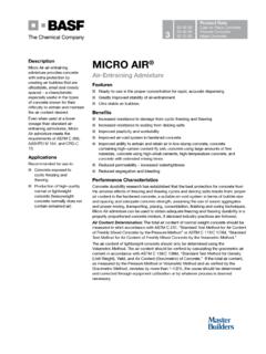
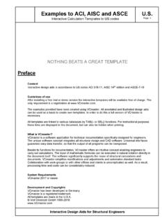
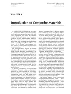
2 Long columns, columns with small cross-sectional dimensions, and columns with little end restraints may develop secondary stresses associated with Column deformations, especially if they are not braced laterally. These columns are referred to as "slender columns". Fig. 3-1 illustrates secondary moments generated in a slender Column by P- effect. Consequently, slender columns resist lower axial loads than Short columns having the same cross-section. This is illustrated in Fig. 3-1. Failure of a slender Column is initiated either by the material failure of a section, or instability of the Column as a member, depending on the level of slenderness.
3 The latter is known as Column buckling. Design of slender columns is discussed in Chapter 4. The classification of a Column as a Short Column or a slender Column is made on the basis of its Slenderness Ratio, defined below. Slenderness Ratio: kl u / r where, l u is unsupported Column length; k is effective length factor reflecting end restraint and lateral bracing conditions of a Column ; and r is the radius of gyration reflecting the size and shape of a Column cross-section. A detailed discussion of the parameters involved in establishing the slenderness ratio is presented in Chapter 4.
4 Columns with slenderness ratios less than those specified in Secs. and for non-sway and sway frames, respectively, are designed as Short columns using this Chapter . 1. Professor Emeritus of Civil Engineering , the University of Texas at Arlington, Arlington, Texas. 2. Professor, Department of Civil and Materials Engineering , University of Illinois at Chicago, Illinois. Non-sway frames are frames that are braced against sidesway by shear walls or other stiffening members. They are also referred to as braced frames. Sway frames are frames that are free to translate laterally so that secondary bending moments are induced due to P- effects.
5 They are also referred to as unbraced frames. The following are the limiting slenderness ratios for Short Column behavior: kl u Non-sway frames: 34 12(M1/M 2 ) ( ). r kl u Sway frames: 22 ( ). r Where the term [ 34 12(M1/M 2 ) ] 40 and the ratio M1/M 2 is positive if the member is bent in single curvature and negative if bent in double curvature. Fig. 3-1 Failure Modes in Short and Slender Columns Column Sectional Capacity In Short columns the Column capacity is directly obtained from Column sectional capacity. The theory that has been presented in Section of Chapter 1 for flexural sections, also applies to reinforced concrete Column sections.
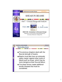
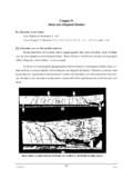
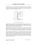
6 However, Column sections are subjected to flexure in combination with axial forces (axial compression and tension ). Therefore, the equilibrium of internal forces changes, resulting in significantly different flexural capacities and behavioral modes depending on the level of accompanying axial load. Fig. 3-2 illustrates a typical Column section subjected to combined bending and axial compression. As can be seen, different combinations of moment and accompanying axial force result in different Column capacities and corresponding strain profiles, while also affecting the failure modes, , tension or compression controlled behavior.
7 The combination of bending moment and axial force that result in a Column capacity is best presented by Column interaction diagrams.. Interaction diagrams are constructed by computing moment and axial force capacities, as shown below, for different strain profiles. Pn = Cc + Cs1 + Cs 2 Ts (3-3). M n = Cc x2 + Cs1 x1 + Ts x3 (3-4). Cs1. Mn Cc tension controlled Pn x1. Cs2 x2. ne h zo ion Balanced section Compression x3. sit controlled Ts an Tr b t= y t = Cross-Section Strain Distribution Stress Distribution Fig. 3-2 Analysis of a Column section Column Interaction Diagrams The Column axial load - bending moment interaction diagrams included herein (Columns through Columns ) conform fully to the provisions of ACI 318-05.
8 The equations that were used to generate data for plotting the interaction diagrams were originally developed for ACI Special Publication SP-73. In addition, complete derivations of the equations for square and circular columns having the steel arranged in a circle have been published in ACI Concrete International4. The original interaction diagrams that were contained in SP-7 were subsequently published in Special Publication SP-17A5. The related equations were derived considering the reinforcing steel to be represented as follows: (a) For rectangular and square columns having steel bars placed on the end faces only, the reinforcement was assumed to consist of two equal thin strips parallel to the compression face of the section.
9 (b) For rectangular and square columns having steel bars equally distributed along all four faces of the section, the reinforcement was considered to consist of a thin rectangular or square tube. (c) For square and circular sections having steel bars arranged in a circle, the reinforcement was considered to consist of a thin circular tube. The interaction diagrams were developed using the rectangular stress block, specified in ACI 318-05. (Sec. ). In all cases, for reinforcement that exists within the compressed portion of the depth perpendicular to the compression face of the concrete (a = c), the compression stress in the steel was reduced by f c/ to account for the concrete area that is displaced by the reinforcing bars within the compression stress block.
10 The interaction diagrams were plotted in non-dimensional form. The vertical coordinate [ K n = Pn /( f c/ Ag ) ] represents the non-dimensional form of the nominal axial load capacity of the 3. Everard and Cohen. Ultimate Strength Design of Reinforced Concrete Columns, ACI Special Publication SP-7, 1964, pp. 152-182. 4. Everard, , Axial Load-Moment Interaction for Cross-Sections Having Longitudinal Reinforcement Arranged in a Circle , ACI Structural Journal, Vol. 94, No. 6, November-December, 1997, pp. 695-699. 5. ACI Committee 340, Ultimate Strength Design Handbook, Volume 2, Columns, ACI Special Publication 17-A, American Concrete Institute, Detroit, MI, 1970, 226 pages.