Transcription of Chapter 9. Shear and Diagonal Tension - Memphis
1 Chapter 9. Shear and Diagonal Tension READING ASSIGNMENT. Text Chapter 4; Sections - Code Chapter 11; Sections , , , , , , and INTRODUCTION OF Shear PHENOMENON. Beams must have an adequate safety margin against other types of failure, some of which may be more dangerous than flexural failure. Shear failure of reinforced concrete, more properly called Diagonal Tension failure is one example. If a beam without properly designed Shear reinforcement is overloaded to failure, Shear col- lapse is likely to occur suddenly with no advance warning (brittle failure). Therefore, concrete must be provided by special Shear reinforcement to insure flexural failure would occur before Shear fail- ure.
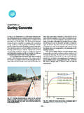
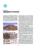
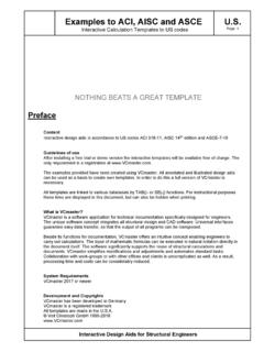
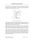
2 In other words, we want to make sure that beam will fail in a ductile manner and in flexure not in Shear . Shear failure of reinforced concrete beam: (a) overall view, (b) detail near right support CIVL 4135. 168 Shear REVIEW OF Shear . Consider a homogenous beam in two sections as shown below. Shearing Stresses are vital part of the beam load carrying capacity. Background Consider a small section of the beam with Shear F1 = 1. 2. MyI + McI (b(c y) ) = M2 c +I y b(c y).. F 2 = 1 M + M dx 2 x c +I y b(c y) = M +2 dM c +I y b(c y). (b)(dx)v = F 2 F 1 = 1 ( M + dM M ). 2. c+y I.. b(c y). ( c + y)(c y). v = dM ( b dx 2) I.. b = V b (c + y)(c y).
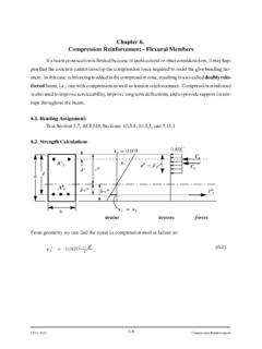
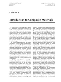
3 Ib 2.. (c y)b (c + y). area 2. arm VQ. v= 1st moment of area below y is called Q. Ib CIVL 4135. 169 Shear BACKGROUND. For a homogenous, rectangular beam Shear stress varies as: max = V. bd Average stress is suitable for concrete analysis max = 3 V. 2 bd How will beam stresses vary? Element 1 at Element 2. Principal Stresses t=. f 2. f4 + r 2. 2. CIVL 4135. 170 Shear Stress trajectories in homogeneous rectangular beam. Tension stresses, which are of particular concern in the view of the low tensile capacity of the concrete are not confined only due to the horizontal bending stresses f which are caused by bending alone. Tension stresses of various magnitude and inclinations, resulting from Shear alone (at the neutral axis); or the combined action of Shear and bending exist in all parts of a beam and if not taken care of appropriately will result in failure of the beam.
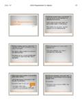
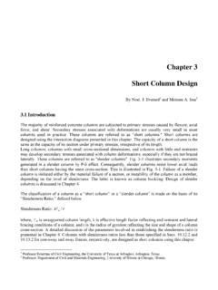
4 It is for this reason that the inclined Tension stresses, known as Diagonal Tension , must be carefully con- sidered in reinforced concrete design. CIVL 4135. 171 Shear ACI318. Figure R CIVL 4135. 172 Shear CRITERIA FOR FORMATION OF Diagonal CRACKS IN CONCRETE BEAMS. Large V ( Shear force), Small M (bending moment). Little flexural cracking prior to formation of Diagonal cracks. v ave = V. bd can be regarded as rough measure of stress Distribution of V is not known exactly, as reinforced concrete is non-homogeneous. Shear near will be largest Crack from propagates toward edges: called web Shear cracks From Diagonal Tension : Concrete tensile strength is given as: v cr = V = 3 f c 5 f c bd tests shown that the best estimate of cracking stress is v cr = V = f c bd Note: The most common type of Shear crack occurs only under high Shear ; with thin webs.
5 Large V ( Shear force), Large M (bending moment). Formation of flexure cracks precedes formation of Shear cracks. Flexure- v at formation of Shear cracks is Shear Crack actually larger than for web Shear cracks. Presence of Tension crack reduces effective Shear area Flexure- Tension Crack CIVL 4135. 173 Shear Formation of flexure Shear crack is unpredictable. Nominal Shear stress at which Diagonal Tension cracks form and propagate is given as V cr (52). v cr = = f c from many tests. bd It was also found that the reinforcement ratio has an effect on Diagonal crack formation for the following reason: As is increased, Tension crack depth decreases; area to resist Shear increases.
6 Based on many tests, ACI-ASCE committee justified the following equation Vc = + 2500 Vd < ACI Equation 11-5.. bd f c M f c . Vd/M term tells that the Diagonal crack formation depends on v and f at the tip of the flexural crack. We can write Shear stress as v = k1 V (53). bd where k1 depends on depth of penetration of flexural cracks. Flexural stress f can be expressed as f = Mc = k 2 M2 (54). I bd where k2 also depends on crack configuration. If we divide (53) by (54) we get v = k 1 V bd 2 = K Vd (55). f k 2 bd M M. where K is determined from experiments. ACI allows us to use an alternate form of Eq. (52) for concrete Shear stress Vc (56).
7 = 2 f c ACI Eq. 11 3. bd Shear cracks in beams without Shear reinforcement cannot be tolerated, can propagate into compres- sion face, reducing effective compression area, area to resist Shear . CIVL 4135. 174 Shear WHAT ACTIONS CONTRIBUTE TO TOTAL Shear RESISTING FORCE - NO Shear REINFORCE- MENTS. Cracked Beam without any Shear reinforcement 1 Force resulting from aggregate interlock at crack. 2. Concrete Shear stress in compression zone 3. Dowel Shear from longitudinal flexural reinforcement. Conservatively, we may neglect all but concrete stress. Nature of failure offers very little reserve capacity if any. As a result, design strength in Shear (without Shear reinforcement) is gov- erned by strength which present before formation of Diagonal cracks.
8 WEB REINFORCEMENT. Shear reinforcement allows for Maximum utility of Tension steel - Section capacity is not limited by Shear Ductile failure mode - Shear failure is not ductile, it is sudden and dangerous. CIVL 4135. 175 Shear POSSIBLE CONFIGURATION OF Shear REINFORCEMENT. Vertical stirrups, also called ties or hoops . Inclined stirrups Bend up bars Generally #3, #4, and #5 bars are used for stirrups and are formed to fit around main longitudinal rebars with a hook at end to provide enough anchorage against pullout of the bars. CIVL 4135. 176 Shear EFFECT OF STIRRUPS. 1. Before Shear cracking - No effect (web steel is free of stress).
9 2. After Shear cracking Resist Shear across crack;. Reduce Shear cracking propagation;. Confines longitudinal steel - resists steel bond loss, splitting along steel, increase dowel actions;. Increase aggregate interlock by keeping cracks small. 3. Behavior of members with Shear reinforcement is somewhat unpredictable - Current design procedures are based on: Rational analysis;. Test results;. Success with previous designs. DESIGN OF Shear REINFORCEMENT - A RATIONAL (!) APPROACH. 1. Before cracking - Cracking load given as before: . V c = bd f c + 2500 w Vd M. f c bd 2. After cracking Assuming Vc equals to that at cracking - This is conservative due to the effect of compression and Diagonal Tension in the remaining uncracked, compression zone of the beam.
10 CIVL 4135. 177 Shear BEAMS WITH VERTICAL STIRRUPS (OR BEAMS WITH Shear REINFORCEMENT). Forces at Diagonal crack in a beam with vertical stirrups can be shown as V N = total internal Shear force = V cz + A vf v + V d + V iy where Vcz = Internal vertical force in the uncracked portion of concrete Vd = Force across the longitudinal steel, acting as a dowel Viy = Aggregate interlock force in vertical direction Av fv = Vertical force in stirrups. If horizontal projection of the crack is p , and the stirrup spacing is s , then the number of stirrups crossed by a random crack will be: p n = s and total force contributed by stirrups will be: V s = nA vf s which near failure will be V s = nA vf y fs = fy Also, we can conservatively neglect forces due to dowel and aggregate interlock.