Transcription of 5 CHAPTER 5: TORSION
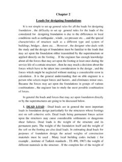
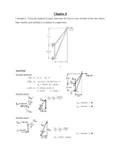
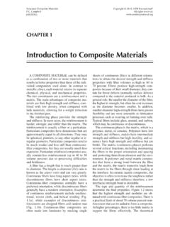
1 1 5 chapter 5 : TORSION Introduction If external loads act far away from the vertical plane of bending, the beam is subjected to twisting about its longitudinal axis, known as TORSION , in addition to the shearing force and bending moment. TORSION on structural elements may be classified into two types; statically determinate, and statically indeterminate. In Figures through several examples of beams subjected to TORSION are shown. In these figures, TORSION results from either supporting a slab or a beam on one side only, or supporting loads that act far away transverse to the longitudinal axis of the beam. Shear stresses due to TORSION create diagonal tension stresses that produce diagonal cracking.
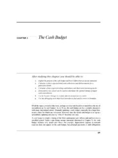
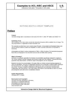
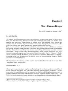
2 If the member is not adequately reinforced for TORSION , a sudden brittle failure can occur. Since shear and moment usually develop simultaneously with TORSION , a reasonable design should logically account for the interaction of these forces. However, variable cracking, the inelastic behavior of concrete, and the intricate state of stress created by the interaction of shear, moment, and TORSION make an exact analysis unfeasible. The current TORSION design approach assumes no interaction between flexure, shear and TORSION . Reinforcement for each of these forces is designed separately and then combined. 2 Figure : Reinforced concrete members subjected to TORSION : (a) spandrel beam; (b)&(c) loads act away from the vertical plane of bending; (d) curved beam; (e) circular beam Shear Stresses Due to TORSION In a rectangular solid section, assuming elastic behavior, the shearing stresses vary in magnitude from zero at the centroid to a maximum at midpoints of the long sides as shown in Figure The maximum shear stress max is given as yxT2max = ( ) (a) (b) (c) (d) (e) 3 where x is the shorter side of the section, y is the longer side of the section, and is a constant in terms of xy.
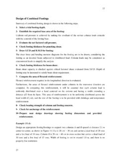
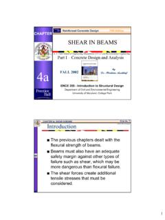
3 A close approximation to is += ( ) Uncracked concrete members behavior is neither perfectly elastic nor perfectly plastic. However, elastic-based formulas have been satisfactorily used to predict torsional behavior. Both solid and hollow members are considered as tubes. Experimental test results for solid and hollow beams with the same outside dimensions and identical areas of TORSION reinforcement, shown in Figure , suggest that once torsional cracking has occurred, the concrete in the center of the member has a limited effect on the torsional strength of the cross section and thus can be ignored. In 1995, the ACI Code analyzed solid beams as hollow beams for which equations for evaluating shear stresses are easier to develop.
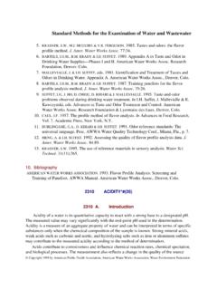
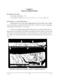
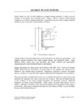
4 Figure : Shear stresses in a rectangular section 4 Figure : Ultimate torsional strength of solid and hollow sections of the same size Principal Stresses Due to Pure TORSION When the beam shown in Figure is subjected to pure TORSION , shearing stresses develop in the four faces as shown by the elements. The principal stresses on these elements are shown in Figure The principal tensile strength is equal to the principal compressive stress and both are equal to the shearing stress . Ultimately, when the principal tensile strength exceeds the maximum tensile strength of the beam, cracking will occur spiraling around the outside surface of the beam as shown in Figure In a reinforced concrete member, such a crack would cause brittle failure unless torsional reinforcement is provided to limit the growth of this crack.
5 Closed stirrups and longitudinal bars in the corners of the section are usually used as torsional reinforcement. 5 (c) Figure : Principal stresses and cracking due to pure TORSION : (a) shear stresses; (b) principal stresses; (c) crack Principal Stresses Due to TORSION , Shear, and Moment If a beam is subjected to TORSION , shear, and bending, the two shearing stresses add on one side face and counteract each other on the opposite face, as shown in Figure Therefore, inclined cracks start at the face where the shear stresses add (crack AB) and extend across the extreme tension fiber. If the bending moment is large, the crack will extend almost vertically across the back face (crack CD).
6 The compressive stresses at the bottom of the cantilever beam prevent the cracks from extending all the way down the full height of the front and back faces. (b) (a) 6 (c) Figure : Combined shear, TORSION and moment: (a) shear stresses due to pure TORSION ; (b) shear stresses due to direct shear; (c) crack TORSION in Thin-walled Tubes Thin-walled tubes of any shape can be quite simply analyzed for the shear stresses caused by a torque applied to the tube. We will consider here an arbitrary cross-sectional shape subjected to pure TORSION by torques T applied at the ends. Furthermore, all cross sections of the tube are assumed to be closed and have similar dimensions and the longitudinal axis is a straight line.
7 The shear stresses acting on the cross section are shown in Figure , which shows an element of the tube cut out between two cross sections at distance dx. The intensity of the shear stresses varies across the thickness of the tube. Since the tube is thin, we may assume to be constant across the thickness of the tube. From equilibrium of forces in the x-direction, (b) (a) 7 cFbF= ( ) Where dxbtbbF = ( ) and dxctccF = ( ) Where bt and ct is tube thickness at points b and c, respectively. Equating Eq. ( ) and ( ) gives dxctcdxbtb = or, ctcbtb = ( ) Therefore, the product of the shear stress and the thickness of the tube t is constant at every point in the cross section.
8 This product is known as the shear flow and denoted by the letter q, and Eq. ( ) can be written as constant==tq ( ) The largest shear stress occurs where the thickness of the tube is smallest, and vice versa. When the thickness is constant, the shear stress is also constant. To relate the shear flow q to the torque T, consider an element of area of length ds, where ds is measured along the centerline of the cross section. The total shear force acting on this element of is dsq, and the moment of this force about any point O is dsqrdT=, where r is the perpendicular distance from point O to the line of action of the force. The torque produced by shear is obtained by integrating along the entire length of centerline of the cross section, given by =dsrqT ( ) 8 Figure : Shear stresses in a thin-walled tube The quantity dsr represents twice the area of the shade triangle shown in Figure Therefore, the integral dsr represents double the area oA enclosed by the centerline of the cross section, or oAdsr2= ( ) Substituting Eq.
9 ( ) into Eq. ( ) gives oAqT2= ( ) Using Eq. ( ) and ( ), one gets (a) (c) (b) (e) (d) 9 tATq ==o2 ( ) From Eq. ( ) the shear stress is given by tATo2= ( ) Eq. ( ) and ( ) apply to any shape in the elastic range. In the inelastic range Eq. ( ) applies only if the thickness t is constant. Current ACI Code Design Philosophy The current design procedure for TORSION is based on the following assumptions: Concrete strength in TORSION is neglected. TORSION has no effect on shear strength of concrete. TORSION stress determination is based on thin-walled tube, space truss analogy. Both solid and hollow members are considered as tubes before and after cracking, and resistance is assumed to be provided by the outer part of the cross section centered around the stirrups.
10 No interaction exists between moment, shear, and TORSION . Reinforcement for each of the three forces is calculated separately and then combined. The basic design equation for TORSION is nuTT = ( ) Where uT is the factored torque, nT is the nominal torsional capacity, and is the strength reduction factor for TORSION , taken as Limit on Consideration of TORSION In pure TORSION , the principal tensile stress 1 , shown in Figure , is equal to the shear stress at a given location. From Eq. ( ) for a thin-walled tube, tATo21== ( ) 10 Where t is the wall thickness at a point where the shear stress is being computed and oA is the area enclosed by the centerlines of the wall thicknesses.