Example: dental hygienist
Chapter 5 Using Sources and Stimuli - Class Home Pages
The first example specifies a pulse source connected between node 3 and node 0. The pulse has an output high voltage of 1 V, an output low voltage of -1 V, a delay of 2 ns, a rise and fall time of 2 ns, a high pulse width of 50 ns, and a period of 100 ns. The second example specifies pulse value parameters in the .PARAM statement. Single pulse ...
Tags:
Information
Domain:
Source:
Link to this page:
Documents from same domain

Enabling High Penetrations of Solar PV for Southern ...
class.ece.uw.educost required to integrate high penetration of PV on numerous feeders. 5 100% Get Solar PV penetration in California to Know current ... Determine native Solar PV penetration levels for representative ... Project Sponsors California Public Utilities Commission, California Solar Initiative, Itron For more information, including project reports ...

Quartus II Testbench Tutorial
class.ece.uw.edu3) Create your Unit Under Test & Testbench Next we will write the Verilog code that we want to test. This code can go in the same file as the top-level, but it is good practice for separate modules to have their own files, so we will do that in this example. For this tutorial the code that we want to test will be a simple 2 to 1 multiplexor ...

Chapter 14 BJT Models - University of Washington
class.ece.uw.eduFor both the vertical and lateral the resistor model parameters, RB, RBM, RE, and RC are scaled by the following equation. where R is either RB, RBM, RE, or RC. BJT Current Convention The direction of current flow through the BJT is assumed for example purposes in Figure 13-1. Use either I(Q1) or I1(Q1) syntax to print the collector current.
Embedded System Design: A Unified Hardware/Software …
class.ece.uw.eduSep 27, 1999 · implementation. The first trend makes the past separation of software and hardware design nearly impossible. Fortunately, the second and third trends enable their unified design, by turning embedded system design, at its highest level, into the problem of selecting (for software), designing (for hardware), and integrating processors.
Programming 8bit PIC Micro Controllers in C
class.ece.uw.eduProgramming 8-bit PIC Microcontrollers in C: With Interactive Hardware Simulation. It completes a set that introduces embedded application design using the Microchip PIC ® range, from Microchip Technology Inc. of Arizona. This is the most popular microcontroller for education and training, which is also rapidly gaining ground in the
Chapter 16 Selecting a MOSFET Model - UWECE
class.ece.uw.eduND V-1 0.0 drain subthreshold factor N0 0.0 gate subthreshold factor. Typical value=1. Name(Alias) Units Default Description. hspice.book : hspice.ch17 11 Thu Jul 23 19:10:43 1998 Selecting a MOSFET Model Level 2 IDS: Grove-Frohman Model Star …
Verilog: Blocks - UWECE
class.ece.uw.eduVerilog: always@ Blocks Chris Fletcher UC Berkeley Version 0.2008.9.4 September 5, 2008 1 Introduction Sections1.1to1.6discuss always@ blocks in Verilog, and when to use the two major avors of always@ block, namely the always@( * ) and always@(posedgeClock) block. 1.1 always@ Blocks always@ blocks are used to describe events that should happen under …

Chapter 9 AC Sweep and Signal Analysis - UWECE
class.ece.uw.eduAC Nodal Voltage Output Syntax Vx (n1,<,n2>) where: x specifies the voltage output type (see Table 9-1:) n1, n2 specfies node names. If n2 is omitted, ground (node 0) is assumed. Example.PLOT AC VM(5) VDB(5) VP(5) The above example plots the magnitude of the AC voltage of node 5 using the output variable VM.

Chapter 7 Performing Transient Analysis - Class Home Pages
class.ece.uw.eduChapter 7 Performing Transient Analysis ... The following performs an analysis for each load parameter value at 1 pF, 5 pF, and 10 pF..TRAN 10NS 1US SWEEP load POI 3 1pf 5pf 10pf The following example is a data driven time sweep and allows a data file to be used as sweep input. If the parameters in the data statement are controlling

Chapter 6 DC Initialization and Point Analysis
class.ece.uw.eduInitialization is fundamental to the operation of simulation. Star-Hspice starts any analysis with known nodal voltages or initial estimates for unknown voltages and some branch currents, and then iteratively finds the exact solution.
Related documents
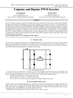
Unipolar and Bipolar PWM Inverter
www.ijirst.orgIn SPWM (Sinusoidal Pulse Width Modulation) two signals are compared. The Modulating reference signal is sinusoidal and the carrier wave is triangular. Gating pulses are produce by comparing the two signals and the width of each pulse is varied is proportion to the amplitude of the sine wave .
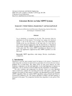
Literature Review on Solar MPPT Systems
ripublication.comphase AC voltages at the output of inverter which was controlled with sinusoidal pulse width modulation (SPWM) scheme. S. G. Tesfahunegn et al. designed a new solar/battery charge controller that combines both MPPT and over-voltage controls as single control function [10]. A small-signal model of lead acid battery was derived in detail to ...

ELE745 Assignment and Lab Manual - Ryerson University
www.ee.ryerson.ca) times the convolution of their spectra. From width property of the convolution, the width of the convoluted signals is the sum of the widths of the signals convolved. Therefore, the BW of the product is 25+50=75 Hz. The Nyquist rate is 150 Hz. 3. Lathi 6.1-4: The BW of the signal g(t) is 5 Hz (10… rad/s), since the FT as below: g(t) = sinc2 ...