Search results with tag "Pulse width"

The Transistor Tester user manual
img.banggood.comThe function ”10-bit PWM” (Pulse Width Modulation) generates a fixed frequency(7812.5Hz) with selectable pulse width at the pin TP2. With a short key press (< 0.5 s) the pulse width is increased by 1%, with a longer key press the pulse width is increased by 10%. If 99% is overstepped, 100% is subtracted from the result.

CHAPTER 2 SINGLE PHASE PULSE WIDTH MODULATED …
www.tntech.edu2.2.1 Pulse Width Modulation Control The fundamental magnitude of the output voltage from an inverter can be controlled to be constant by exercising control within the inverter itself that is no external control circuitry is required. The most efficient method of doing this is by Pulse Width Modulation (PWM) control used within the inverter.
Chapter 5 Using Sources and Stimuli - Class Home Pages
class.ece.uw.eduThe first example specifies a pulse source connected between node 3 and node 0. The pulse has an output high voltage of 1 V, an output low voltage of -1 V, a delay of 2 ns, a rise and fall time of 2 ns, a high pulse width of 50 ns, and a period of 100 ns. The second example specifies pulse value parameters in the .PARAM statement. Single pulse ...

TL494, NCV494 SWITCHMODE Pulse Width …
www.onsemi.com© Semiconductor Components Industries, LLC, 2005 June, 2005 − Rev. 6 1 Publication Order Number: TL494/D TL494, NCV494 SWITCHMODE™ Pulse Width Modulation Control Circuit The TL494 is a fixed frequency, pulse width modulation control
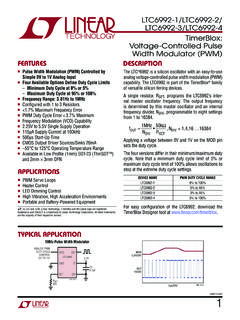
LTC6992-1 (Rev. D) - Analog Devices
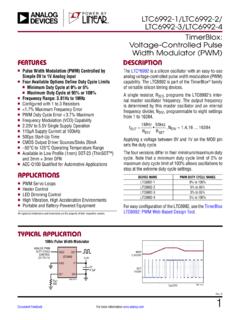
www.analog.comVoltage-Controlled Pulse Width Modulator (PWM) The LTC®6992 is a silicon oscillator with an easy-to-use analog voltage-controlled pulse width modulation (PWM) capability. The LTC6992 is part of the TimerBlox® family of versatile silicon timing devices. A single resistor, RSET, programs the LTC6992s inter’ - nal master oscillator frequency.

SPEED CONTROL OF DC MOTOR USING PULSE WIDTH …
rcciit.org.in8. Pulse Width Modulation Waveform 13-14 9. Block Diagram of an Analogue PWM Generator 14 10. Block Diagram 18 11. 12V Power Supply 19 12. Pin Diagram of IC555 Timer 21 13. IC555 Timer 23 14. Darlington Pair npn Transistor 23 15. TIP122 24
LTC6992-1/LTC6992-2/ LTC6992-3/LTC6992-4 - …
www.analog.comLTC6992-1/LTC6992-2/ LTC6992-3/LTC6992-4 1 69921234fc Typical applicaTion DescripTion TimerBlox: Voltage-Controlled Pulse Width Modulator (PWM) The LTC®6992 is a silicon oscillator with an easy-to-use analog voltage-controlled pulse width modulation (PWM)

MSP430 Interrupts - courses.cs.washington.edu
courses.cs.washington.eduPulse width modulation (PWM) is used to control analog circuits with a processor's digital outputs PWM is a technique of digitally encoding analog signal levels The duty cycle of a square wave is modulated to encode a specific analog signal level

AD9910 (Rev. E) - Analog Devices
www.analog.comI/O_UPDATE Pulse Width High >1 SYNC_CLK cycle Minimum Profile Toggle Period 2 SYNC_CLK cycles TxENABLE and 16-BIT PARALLEL (DATA) BUS TIMING . Maximum PDCLK Frequency . 250 . MHz . TxENABLE/Data Setup Time (to PDCLK) 1.75 . ns . TxENABLE/Data Hold Time (to PDCLK) 0 . ns . MISCELLANEOUS TIMING CHARACTERISTICS . Wake-Up …

ABB drives, Technical guide No. 1 Direct torque control ...
library.e.abb.comBoth voltage and frequency reference are fed into a modulator which simulates an AC sine wave and feeds this to the motor’s stator windings. This technique is called pulse width modulation (PWM) and utilises the fact that there is a diode rectifier towards the mains and the intermediate DC voltage is kept constant.

LM555 Timer datasheet (Rev. D)
www.ti.comControl Controls the threshold and trigger levels. It determines the pulse width of the output 5 Voltage I waveform. An external voltage applied to this pin can also be used to modulate the output waveform Discharge Open collector output which discharges a capacitor between intervals (in phase with output). 7 I
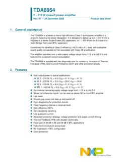
TDA8954 2 × 210 W class-D power amplifier - NXP
www.nxp.comFor each channel, the audio input signal is co nverted into a digital Pulse Width Modulation (PWM) signal using an analog input stage and a PWM modulator; see Figure 1. To drive the output power transistors, the digital PWM signal is fed to a control and handshake block and to high- and low-side driver circuits .

High-Speed, Microcontroller-Adaptable, Pulse Width Modulator
ww1.microchip.com2004-2013 Microchip Technology Inc. DS21896C-page 5 MCP1630/MCP1630V Typical Application Circuit - MCP1630V Bidirectional Power Converter/Battery Charger for 4-Series Cell Li-Ion Batteries

Pulse Width Modulated (PWM) Drives
literature.rockwellautomation.comPulse Width Modulated (PWM) drives. In this type of drive, a ... Modulation Generator PWM. The triangular signal is the carrier or switching frequency of the ... Field Oriented Control Block Diagram Pulse Width Modulated (PWM) Below is a plot of a drive using the Sensorless version of Force Technology.