Transcription of Chapter 6 Digital Input (DI) Circuit - SEA Praha
1 H6-1 Chapter 6 Digital Input (DI) Circuit The FBS-PLC provides the ultra high speed differential double end 5 VDC inputs ( , single Input with two terminals without common) and the single-end 24 VDC inputs which use the common terminal to save terminals. The response speeds of single-end common Input circuits are available in high, medium and low. Because the double end Input Circuit has two independent terminals, it can be connected either in SINK or SOURCE for Input or in differential Input wiring for line driver source. The single-end Input Circuit can be set to SINK or SOURCE type by varying the wiring of the common terminals S/S inside PLC and external common wire of Input circuits (see Sec.)
2 For details). Specifications of Digital Input (DI) Circuit Item Specifications 5 VDC Differential Input 24 VDC Single-end Input Note Ultra High Speed(HSC) High Speed (HSC) Medium Speed(HSC) Mid/Low Speed Low SpeedMaximum Input frequency*/ accumulated time 920 KHz 200 KHz 20 KHz (HHSC)Total 5 KHz (SHSC) mS*1 mS *: Half of maximum frequency while A/B phase inputInput Signal Voltage 5 VDC 10% 24 VDC 10% Input Current Threshold ON Current 11 mA 8 mA 4mA OFF Current 2 mA Maximum Input current 20mA mA Input Status Indication Displayed by LED.
3 Lit when ON , dark when OFF Isolation Type Photocoupler signal isolation SINK/SOURCE Wiring Independent Wiring Via variation of internal common terminal S/S and external common wiring List of Input Response Speed for Various Models FBS-20 MNR/T/J X0,1 X4, 5, 8, 9 X2,3,6,7,10,11 *1 Limit of Input speed in MAmodel is 10 KHz FBS-32 MNR/T/J X0,1,4,5 X8, 9, 12, 13 X2,3,6,7,10,11,14,15 X16~19 FBS-44 MNR/T/J X0,1,4,5,8,9,12,13 X2,3,6,7,10,11,14,15 X16~27 FBS-10 MCR/T/J X0,1 X4,5 X2,3 FBS-14 MCR/T/J X0,1 X4,5 X2,3,6,7 FBS-20 MCR/T/J X0,1,4,5 X8,9 X2,3,6,7,10,11 FBS-24 MCR/T/J X0,1,4,5 X8, ,13 X2,3,6,7,10,11 FBS-32 MCR/T/J X0,1,4,5,8,9 X12,13 X2,3,6,7,10,11,14,15 X16~19 FBS-40 MCR/T/J X0,1,4,5,8,9 X12,13 X2,3,6,7,10,11,14,15 X16~23 FBS-60 MCR/T/J X0,1,4,5,8,9,12,13 X2,3,6,7,10,11,14,15 X16~35 FBS-10 MAR/T/J X0,1,4,5 X2,3 FBS-14 MAR/T/J X0,1,4,5 X2,3,6.
4 7 FBS-20 MAR/T/J X0,1,4,5,8,9 X2,3,6,7,10,11 FBS-24 MAR/T/J X0,1,4,5,8,9,12,13 X2,3,6,7,10,11 FBS-32 MAR/T/J X0,1,4,5,8,9,12,13 X2,3,6,7,10,11,14,15 X16~19 FBS-40 MAR/T/J X0,1,4,5,8,9,12,13 X2,3,6,7,10,11,14,15 X16~23 FBS-60 MAR/T/J X0,1,4,5,8,9,12,13 X2,3,6,7,10,11,14,15 X16~35 Expansion Unit/Module R/T/J All Input Points Noise Filtering Time Constant*3 DHF(0 ~ 15mS) AHF( s) DHF(0 ~ 15mS) AHF( s) DHF(0 ~ 15mS) AHF( s) AHF( )DHF Digital Hardware Filter AHF Analog Hardware Filter H6-2 Structure and Wiring of 5 VDC Ultra High Speed Differential Input Circuit Only the MN main unit of FBs provides the 5 VDC ultra high speed differential Input Circuit , which is mainly used for the Input of hardware high speed counter (HHSC) with a maximum working frequency up to 920 KHz.
5 In practice, to ensure the high speed and high noise immunity, please use Line-Driver for differential line driving. In environments with small noise and medium working frequency ( 200 KHz), however, it can be changed to the 5 VDC single-end SINK or SOURCE Input or to the 24 VDC single-end SINK or SOURCE Input by connecting a 3K resistor in series, as shown in the figure below. (A) Wiring of 5 VDC differential Input for Line-Driver driving with frequency up to 920 KHz for high speed and environments with large noise FBS-MN Line-Driver B A (B) Wiring of 5 VDC differential Input to 5 VDC single SINK or SOURCE Input X1+X1X0X0+PNPSENSORSOURCE NPNSENSORSINK 5 VDCR1R2R1R2 FBS-MN main unit (C) Method of converting 5 VDC differential Input to 24 VDC single-end SOURCE Input Twisted-pair (Encoder) External differential output FBs-MN main unit Dual-end Input SOURCE Input SINK inputSOURCE X1X1+X0X0+FBS-MN 24 VDC3K NPNSENSORR1R2R1R2 FBs-MN main unit SINK Input SOURCE Input R1.
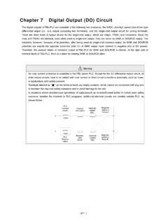
6 100 R2 H6-3 24 VDC Single-End Input Circuit and Wiring for SINK/SOURCE Input The 24 VDC single-end Digital Input circuits of FBS-PLC are available for high, medium and low speed. They all have the similar Circuit structures but with different response speeds. To save Input terminals, the Circuit of single-end Input is implemented by connecting one end of all Input points (photo coupler) inside the PLC to the same internal common point labeled as S/S. The other end of each Input Circuit is connected to corresponding terminals such as X0, X1, X2, etc. The S/S common terminal and N single-end inputs comprise of N Digital inputs ( , only N+1 terminals are used for N terminals).
7 Therefore, we call this type of Input structure the single-end Input . The user also needs to do the same thing when making the connection of external Digital Input devices. Namely, the one end of all Input devices ( , buttons, switches) are connected together and called the external common wire, while the other ends of Input circuits are connected to the Input terminals X0, X1, X2, etc., of PLC. Then finish it by connecting the external common wiring and internal common terminal S/S to the positive/negative terminals of the 24 VDC power. When connect the internal common terminal S/S to 24V+(positive) and the external common wire to 24V (negative), then the Circuit serve as SINK Input .
8 On the contrary, while exchange the wiring of the above internal and external common will serve as a SOURCE Input . The above wiring schemes can illustrated below: z Wiring of single-end common SINK Input R2R2R2R2 FBS |PLC24 VDC( )X0X1X2X3S/S NPNS ensor24V-24V+ 24 VDC X1X2X0R1 R1R1X3R1 z Wiring of single-end common SOURCE Input FBS |PLCX024 VDC( )X1X2X3 PNPS ensor 24V+24V- S/SX024 VDC X3X1X2 R1R1R2R2R2R1R2R1 External Common WiringExternal Common WiringExternal Power (not available in expansion modules) Input Circuit Input devices (not available in expansion modules) Internal Common Te r m i n a lExternal Power Internal Common Te r m i n a lLow speed R1 R2:1K Middle speed R1 R2