Transcription of Chapter 5 Power Supply Wiring, Power …
1 H5-1 Chapter 5 Power Supply wiring , Power consumption calculation , and Power sequence requirements FBS-PLC internally has three kinds of circuit: a 5 VDC logic circuit, a 24 VDC driver circuit (driver output devices, for example: relay, transistor, and etc), and a 24 VDC input circuit. Only the 5 VDC logic circuit and 24 VDC output circuit are powered by the built-in Power Supply for main/expansion units or powered by expansion Power Supply modules (FBs-EPW-AC, FBs-EPW-D24), and the 24 VDC input circuit can be choose to powered by the external Power Supply or the built-in Power Supply of main/expansion units or 24 VDC sensor of FBs-EPW-AC/D12/D24. Expansion modules other than main/expansion units do not contain any Power Supply and are powered by the Power Supply inside the main/expansion units or expansion Power Supply (FBS-EPW-AC, FBs-EPW-D24).
2 Main/expansion units or expansion Power Supply with their model numbers suffixed with -D12/-D24 means is operated by DC Power source. Otherwise, AC Power source is used. Caution In industrial environments, main Power may irregularly experience a surge current or high voltage pulse caused by the start or shut down of high Power equipment. Users are advised to take necessary measures (for example, the use of isolation transformer or other MOV suppression devices) for the protection of PLC and its peripherals. Specifications and wiring of AC Power Sourced Power Supply The available AC Power supplies of FBS-PLC are the 14 Watt (SPW14-AC) Supply for 10/14 PTs main unit, the 24 Watt (SPW24-AC) Supply for 20~60 PTs main/expansion unit, and the 14 Watt expansion Supply (FBS-EPW-AC) for expansion modules. Except that the FBS-EPW-AC is an independent module, SPW14-AC and SPW24-AC are to be installed on a main unit or inside an expansion unit, where their appearances are invisible.
3 The following table lists the specifications: Model Item SPW14-AC SPW24-AC FBS-EPW-AC Input Range Voltage 100 ~ 240 VAC, -15% / +10% Frequency 50 / 60HZ 5% Max. Power consumption 21W / 14W 36W / 24W 21W / 14W Inrush Current 20A@264 VAC Allowable Power Interrupt 20ms Fuse Spec. 2A 250V Isolation Type Transformer/Photocouple Isolation, 1500 VAC/minute Power *1 Output 5 VDC (logic circuit) N/A*2 5V, 5%, 1A(max) 5V, 5%, (max) 24 VDC (output circuit) 24V 10%, 200mA(max)*324V, 10%, 400mA(max)24V, 1%, 250mA(max)24 VDC (input circuit) 24V, 10%, 400mA(max)24V, 10%, 400mA(max) 24V, 10%, 250mA(max) Note *1 The 5 VDC (for logic circuit) output Power and the 24 VDC (for output circuit) Power can be accessed from the I/O expansion output header located on the right side of the main/expansion units for expansion modules. And the 5 VDC Power is also used by communication board (CBxx) or communication module (CMxx).
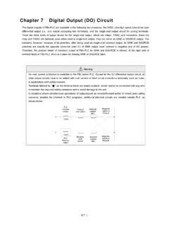
4 The 24 VDC Power for input circuits is provided from the farthest 2 upper left terminals (labeled +24V OUT- ) on the input terminal block of main/expansion unit to input circuit in expansion module or other sensors. SpecH5-2 Note *2 The 5 VDC Power of 10/14 PTs main unit is generated from the 24 VDC Power in the output circuit, with specifications of 5 VDC 10% and 400mA (max) (Circuit is located on the I/O board of 10/14 PTs main unit). Note *3 Without any I/O expansion interface, the 24 VDC Power in 10/14 PTs main unit is for its output circuit alone and cannot be used for other purposes. Caution The schematic diagram of AC Power Supply wiring in main/expansion units is shown below. Also be cautious about the following: Please follow the wiring schemes regulated by local national standards to use single-pole switch break hot wire L , or double-pole switch break both L and N , to turn on or off the AC input Power .
5 In wiring , hot wire L must be connected to the L terminal on unit, while the ground line N connected to theN terminal. Please use wires with diameters 1mm2 2mm2. All G terminals on main unit and expansion unit/module have to be connected to the EG (Earth Ground) terminal of main Power system as shown in the figure below, with wire diameters larger than 2mm2. (FBS- )24 VDCexternal powerExpansion module100-240 VACmain powerLNPEO utputMain unit(FBS- M )SWInputCPU0V5V24V0 VAC-DCPowerSupplyF24 VOUTOR24 VDC output (for Input/Sensor)(FBS-6AD, 2DA, 6TC, )24 VDCexternal powerExpansion moduleExpansion unitOutputOutput(FBS- XYAC)controlInputF24V0V0V24V5 VcontrolOUTI nputAIExpansion Power Supply (FBS-EPWAC)5VF0V24V24V0 VOUT controlORINCONVERTER(DC-DC)AC-DCPowerSup plyAC-DCPowerSupply24 VDC output (for Sensor) input /Sensor input /Sensor input /Sensor24 VDC output (for Sensor)SPW24-ACSPW24-AC Specifications and wiring of DC Power Sourced Power Supply The available DC Power sourced Power supplies of FBS-PLC are the 14 Watt (SPW14-D12/D24) Supply for 10/14 PTs main unit, the 24 Watt (SPW24-D/12D24) Supply for 20~60 PTs main/expansion unit, and the 14 Watt expansion Supply (FBS-EPW-D24) for expansion modules.
6 Besides the FBS-EPW-D24 is an independent module, SPW14-D12/D24 and SPW24-D12/D24 are to be installed on a main unit or inside an expansion unit, where their appearances are invisible. The following table lists the specifications: Warning Output of Power for sensor cannot be connected in parallel with other powers, in which the conflict between two sets of Power will decrease their lifetime or cause immediate damage. This will induce unexpected malfunction of PLC and cause serious or even deadly damage to people or equipment. H5-3 Model Item SPW14-D12/D24 SPW24-D12/D24 FBS-EPW-D24 Rated Voltage 12 or 24 VAC, -15%/+20% 24 VAC, -15%/+20% Max. Power consumption 21W / 14W 26W / 24W 21W / 14W Inrush Current 20A @ 12 or 24 VDC 20A@24 VDC Allowable Power Interrupt 20ms Fuse Spec. 3A(D12) (D24), 125V5A(D12) (D24), 125V , 125V Isolation Type Transformer/Photo Coupler Isolation, 500 VDC/minute Power *1 Output 5 VDC(logic circuit) N/A*2 5V, 5%, 1A(max) 5V, 5%, (max) 24 VDC(output circuit) 24V 10%, 200mA(max)*324V, 10%, 400mA(max) 24V, 10%, 250mA(max)24 VDC(input circuit) 24V 10%, 400mA(max) 24V, 10%, 400mA(max) 24V, 10%, 250mA(max) Note *1 The 5 VDC (for logic circuit) output Power and the 24 VDC (for output circuit) Power can be accessed from the I/O expansion output header located on the right side of main/expansion units for expansion modules.
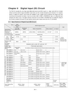
7 The 24 VDC Power for input circuit is provided from the farthest 2 upper left terminals (labeled +24V OUT- ) on the input terminal block of main/expansion unit to input circuit in expansion module or other sensors. Note *2 The 5 VDC Power of 10/14 PTs main unit is generated by the oscillations of the 24 VDC Power in the output circuit, with specifications of 5 VDC 10% and 400mA (max) (Circuit is located on the I/O board of 10/14 PTs main unit) Note *3 Without any I/O expansion interface, the 24 VDC Power in 10/14 PTs main unit is for its output circuit alone and cannot be used for other purposes. Caution The schematic diagram of DC Power Supply in main/expansion unit is shown below. Also be cautious about the following: Please follow the wiring schemes regulated by local national standards to choose single-pole switch (break 24V+) or double-pole switch (break both 24V+ and 24V ) in order to turn on or off DC input Power .
8 wiring of 24V+ input Power must be connected to the terminal labeled by + , while the 24V end is connected to the terminal, Please use wires with diameters of 1mm2 2mm2. The G terminals on main unit and all digital expansion units/modules must be connected to the EG (Earth Ground) terminal on main Power system according to the scheme shown in the following figure, using wire diameters larger than 2mm2. Warning Output of 24 VDC Power for input circuit cannot be connected in parallel with other powers, in which the conflict between two sets of Power will decrease their lifetime or cause immediate damage. This will induce unexpected malfunction of PLC and cause serious or even deadly damage to people or equipment. Expansion unit(FBS- XY-D24)24V0 VOutputPE12 or 24 VDCpowerSWFO utputFCPUI nputDC-DCPowerSupply0V24V5 VOUTMain unit(FBS- M -D)controlInputOUTE xpansion module(FBS- )OutputFAI(FBS-6AD, 2DA, 6TC, )Expansion modulecontrolCONVERTER(DC-DC)Inputcontro l0V24 VOUTE xpansion Power Supply (FBS-EPW-D24)IN5 VDC-DCPowerSupplyDC-DCPowerSupply24 VDCexternal power24 VDC output (for Sensor) input /SensorOR input /Sensor24 VDC output (for Sensor) input /Sensor24 VDC output (for Sensor)24 VDCexternal powerOR5V24V 0V24V 0V24V 0 VSPW24-D24 SPW24-D24 Spec.
9 H5-4 Residual Capacity of Main/Expansion Unit & Current consumption of Expansion Module Besides its own circuits usage, the residual capacities of three sets of built-in Power Supply of main/expansion unit are big enough for other expansion modules usage. In addition, the expansion Power (FBS-EPW) module can also provides the Power for expansion modules usage. As each model of the main/expansion unit has AC/DC Power or modules, it has different residual capacity, various models of expansion modules also consume different amounts of current. In practice, one has to consider the match between the two to avoid overload in any of the three sets of output Power . In the following, the worst case of the available residual capacity in each main/expansion unit and the maximum Power consumption of expansion modules are described below spare.
10 Residual Capacity of Main/Expansion Unit Extra Capacity Model Output Power 5 VDC(logic circuit) 24 VDC(output circuit) 24 VDC(input circuit)-output communication block or expansion cable- -output expansion cable- -output terminal block-AC P O W E R Main Unit FBS-10/14MA 300mA 340mA FBS-20MA 753 mA 335mA 310mA FBS-24MA 722 mA 325mA 295mA FBS-32MA 712 mA 315mA 262mA FBS-40MA 688 mA 295mA 244mA FBS-60MA 644 mA 255mA 190mA FBS-10/14MC 300 mA 340mA FBS-20MC 753 mA 335mA 310mA FBS-24MC 722 mA 325mA 295mA FBS-32MC 712 mA 315mA 262mA FBS-40MC 688 mA 295mA 244mA FBS-60MC 644 mA 255mA 190mA FBS-20MN 710mA 310mA 325 mA* FBS-32MN 670mA 297mA 280 mA* FBS-44MN 627 mA 276 mA 250 mA*