Transcription of Chapter 7 Digital Output (DO) Circuit - GSM …
1 H7-1 Chapter 7 Digital Output (DO) Circuit The Digital outputs of FBS-PLC are available in the following two structures: the 5 VDC ultra high speed Line-driver type differential Output ( , one Output occupying two terminals), and the single-end Output Circuit for saving terminals. There are three kinds of Output device for the single-end Output , which are relays, TRIAC and transistors. Since the relay and TRIAC are bilateral, even when used in single-end Output , they can serve as SINK or SOURCE Output . The transistor, however, because of its polarities, after being used as single-end common Output , its SINK and SOURCE polarities are exactly the opposite (common point Cn of SINK Output must connect to negative end of DC power). Therefore, the product model of transistor Output of FBS-PLC for SINK and SOURCE is distinct.
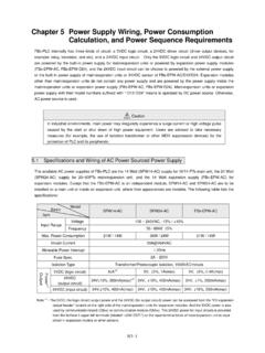
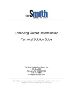
2 At the right side of terminal block of FBS-PLC, there is a place for making SINK or SOURCE label. Warning No over current protection is available in the FBS series PLC. Except for the 5V differential Output Circuit , all other Output circuits have to be added with over current or short Circuit protections externally, such as fuses, in applications with safety concern. Terminals labeled by on the terminal block are empty contacts, which cannot be connected with any wire to maintain the required safety clearance and to avoid damage to the unit. In situations where simultaneous operations of outputs(such as reverse/forward action of motor) pose safety concerns, besides the interlock in PLC programs, additional interlock circuits are needed outside PLC, as shown below PLC PLC B A (NC) (NC) Output PLC Forward Output Forward limit switchMagneticswitch orRelay A Interlock contact (NC) PLC Reverse Output ReverseLimit switchInterlock contact (NC) Magnetic switch or Relay B Output H7-2 Specifications of Digital Output Circuit Item Specification Differential Output Single-End Transistor Output (T, J )
3 Single-End Relay Output Ultra High Speed High Speed Medium Speed Low Speed Maximum Output frequency* 920 KHz 200 KHz20 KHz For ON/OFF, not for frequent exchange Working Voltage 5 VDC 10% 5 30 VDC <250 VAC, 30 VDC Maximum Load Current Resistive 50mA (24YT/J)2A/single, 4A/common Inductive 80VA(AC)/24VA(DC) Maximum Voltage Drop/conducing resistance (initial) Minimum Load 2mA/DC power Leakage Current mA/30 VDC Maximum Output Delay Time ON OFF 200nS 2 S 15 S 10mS OFF ON 30 S Output Status Indication LED is bit when ON , dark when OFF Over Current Protection N/A Isolation Type Photocoupler Isolation, 500 VAC, 1 minute Electromagnetic Isolation, 1500 VAC, 1 minute SINK/SOURCE Output Type Independent Dual Terminals for arbitrary connection Choose SINK/SOURCE by models and non-exchangeable Bilateral device.
4 Can be arbitrarily set to SINK/SOURCE Output List of Input Response Speed for Various Models FBS-20 MNR/T/J Y0~1 Y2~7 Y2~7 FBS-32 MNR/T/J Y0~3 Y4~7 Y8~11 Y4~11 FBS-44 MNR/T/J Y0~7 Y8~15 Y8~15 FBS-10 MCR/T/J Y0,1 Y2,3 All Output points FBS-14 MCR/T/J Y0,1 Y2~5 FBS-20 MCR/T/J Y0~3 Y4~7 FBS-24 MCR/T/J Y0~3 Y4~7 Y8~9 FBS-32 MCR/T/J Y0~5 Y6,7 Y8~11 FBS-40 MCR/T/J Y0~5 Y6,7 Y8~15 FBS-60 MCR/T/J Y0~7 Y8~23 FBS-10 MAR/T/J Y0~3 FBS-14 MAR/T/J Y0~5 FBS-20 MAR/T/J Y0~7 FBS-24 MAR/T/J Y0~7 Y8.
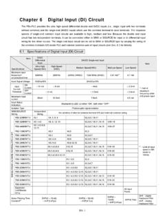
5 9 FBS-32 MAR/T/J Y0~7 Y8~11 FBS-40 MAR/T/J Y0~7 Y8~15 FBS-60 MAR/T/J Y0~7 Y8~23 Expansion Units/Modules(R/T/J) All Output points *Half of the maximum frequency while A/B phase Output H7-3 FBS-XXMN 5 VDC Ultra High Speed Line-Driver Differential Output Circuit and its Wiring The 5 VDC ultra high speed Line-Driver differential Output Circuit of FBS-PLC is only available for the main unit of the MN model. Its Output can connect to general photo coupler Circuit or Line-Receiver input Circuit , with the connection shown in the figure below.
6 To improve noise immunity and maintain signal quality, please use twisted pair with shield (or aluminum foils) for connection and connect the shield with SG of PLC and FG of the driver. Please also operate in 2-phase driving mode (because 2-phase driving can automatically cancel interferences from noise pulses). FBS-MN Line-Driver Photocouple Line-Receiver Single-End Output Circuit Except that the 5 VDC ultra high speed Output Circuit has independent dual terminal outputs, all other Output circuits such as relays, transistors or TRIAC are single-end Output structure. A single-end Output in each Digital Output (DO) takes up only one terminal. But since any Output device has two ends, the one end of several Output devices have to be connected together to one common point (called Output common) for single-end Output .
7 Then each Output point can Output via this common point. The more Output device share a same common points, the more terminals are saved, while relatively increasing the current running through the common point. Combination of any Output common with its individual single-end outputs are called a Common Output Block, which is available in 2, 4 and 8 PTs (high-density module) in FBS-PLC. Each Common Output Block is separated from one another. The common terminal has a label initiated with letter C , while its numbering is determined by the minimum Yn number which comprise the Output block. In the example of the figure below, the number of common terminal of Output block Y2 and Y3 is C2, while the number of common terminal of Output Block Y4, Y5, Y6 and Y7 is C4. The various single-end common Output circuits are described below Structure and Wiring of Single-End Relay Output Circuit Because relay contacts have no polarity, it can be applied for AC or DC load power.
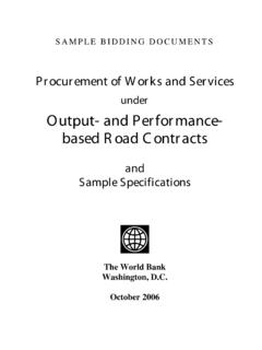
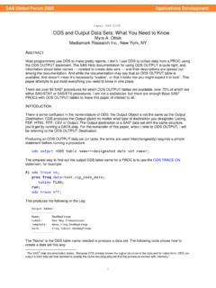
8 Each relay can provide current up to 2A. The maximum rated current in all Output commons of FBS-PLC is 4A. Its mechanical lifetime can reach up to 2 million times, while the contacts have a shorter lifetime. The lifetime also varies depending on working voltage, load type (power factor cos ) and contact current. The relation between them is plotted in the figure below. In the case of pure resistive load (cos = ) at 120 VAC and 2A, the lifetime of contacts is about 250 thousand times. While for high inductive or capacitive load with cos up to and current within 1A, the lifetime decreases rapidly to about 50 thousand times (AC200V) or 80 thousand times (AC120V). Photocouple input Line-Receiver input Load FBS-MN Main Unit Line-Driver Output With frequency up to 920 KHz, for high speed or high noise environments Twisted-pair H7-4 FBS-PLC AC/DC AC/DC cos = (A) cos = = = Structure and Wiring of Single-End Transistor SINK and SOURCE Output Circuit A.
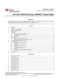
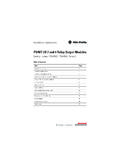
9 Transistor Single-End SINK Output 1 AFUSE2 AFUSE FBS-PLCC2Y2Y3C4Y4Y5Y6Y7 Contact Current (A) Times of Action (ten thousand) AC/DC power2 PTs Common Output Block 4 PTs Common Output Block 4 AFUSE4A FUSE AC/DC power H7-5 B. Transistor Single-End SOURCE Output C2Y2Y3C4Y4Y5Y7 FBS-PLC2 AFUSE 1 AFUSEDC The figure above uses Output block s of 2 PTs common and 4 PTs common as an example to explain the differences in structural and wiring for SINK and SOURCE Output circuits, respectively.(8 PTs common has the same block structure and wiring, except with different point number) The single-end SINK Output and SOURCE transistor Output in FBS-PLC are different models. The user must check whether it is SINK Output model or SOURCE Output model when purchasing. 2 PTs Common Output Block4 PTs Common Output Block DCpowerH7-6 Speed up the Single-End Transistor Output Circuit (only applicable to high and medium-speed) Either with the SINK or SOURCE structure in single-end Output transistor Circuit , when the transistor switches from ON to OFF, the junction capacitor between transistor CE electrodes should be charged to near the load voltage VDD before it can stop the current running through the photocoupler inside the load, which increase the OFF time and decrease the response speed.
10 This problem can be solved by adding a Dummy load to accelerate charging rate and speed up the working frequency of transistor Output . For the transistor Output in FBS-PLC, Dummy load that are added to the high- and medium-speed transistor Output and generate a load current of 20~50mA is adequate. For low speed transistor where its driving capability ( ) but speed is concerned, adding a Dummy load only decreases its driving capability without any significant improvement and hence is not recommended. The following diagram shows how to add a Dummy load to SINK and SOURCE transistor Output . FBS-PLCRVDD5~30 VDCIFBS-PLCRISINK outputSRCE outputVDD5~30 VDCLoadLoad Output Device Protection and Noise Suppression in DO Circuit Since the Digital Output circuits are mainly used for the ON/OFF switching operation, the Output components such as relays, transistors and TRIAC can be deemed as kinds of switch components.