Example: marketing
Chapter 6: Transistors and Gain
1. Measure the current gain of a 2N3904 transistor using the constant current source circuit from design exercise 6-1. If you measure the collector current through the collector/load resistor for a variety of base currents (i.e. change the base resistor or the voltage applied to it), then you should be able to extract a value for β.
Tags:
Information
Domain:
Source:
Link to this page:
Documents from same domain

Report on Lab 2 Thévenin resistance and voltage of a power ...
physics.wm.eduto the operation of the power supply used to power breadboard circuits in the Physics 252 laboratory course. Thévenin's theorem states that any linear power supply can be represented as an ideal voltage source in series with a single resistor, regardless of the inner workings and engineering of the supply [1]. This powerful theorem allows circuit
Chapter 3: Capacitors, Inductors, and Complex Impedance
physics.wm.eduChapter 3: Capacitors, Inductors, and Complex Impedance - 21 - To study a constant supply voltage on an RC circuit, we set the left side of equation 3.12 equal to a constant voltage. Then we have a simple homogeneous differential equation with the simple solution for the current of a decaying exponential, I I e /(t RC) 0

Chapter 9 Ohm’sLaw- Series and Parallel Circuits
physics.wm.eduChapter 9 Ohm’sLaw- Series and Parallel Circuits 9.1 Purpose. Ohm’s law will be explored in this lab using series and parallel circuits. 9.2 Introduction

Chapter 8 The Telescope - Physics
physics.wm.eduChapter 8 The Telescope 8.1 Purpose In this lab, you will measure the focal lengths of two lenses and use them to construct a simple telescope which inverts the image like the one developed by …
EEEE 0 3.40 eV. 24 E 13.6 eV - Physics
physics.wm.eduCollege Physics Chapter 27: Early Quantum Physics and the Photon 1003 (b) Strategy Use Eq. (14-4). Solution Find the temperature increase. 600 J, so 0.48C. 0.30 kg4186 J(kgK) Q QmcTT mc =!!== =¡"# 70.(a) Strategy Use the percent abundance of potassium-40 in the potassium in the broccoli and the atomic masses to find the mass of the potassium-40 in the broccoli.

Chapter 3 Oscillations: Mass on aSpring and Pendulums
physics.wm.eduAn electronic photo-gate timer will be used to measure the period of the different pendulums. The basic apparatus is shown in figure 3.2 • Remove the spring and mass hanger from the arm of the stand. Attach a string of approximately 0.75 meters to the arm of the stand. Attach a 0.05 kg (50 gram) mass to the end of the string.
Related documents
Precision, Very Low Noise, Low Input Bias Current, Wide ...
www.analog.comprecision JFET amplifiers that feature low offset voltage, input bias current, input voltage noise, and input current noise. The combination of low offsets, low noise, and very low input bias currents makes these amplifiers especially suitable for high impedance sensor amplification and precise current measurements using shunts.

How to Simplify the Design of an RF Remote Control Using a ...
www.silabs.comantenna inefficiencies and wasted power. Figure 2 shows a simplified block diagram of the Si4010’s power amplifier and antenna tuning circuitry. An additional feedback loop is incorporated into the power amplifier (PA) to maintain constant output power by monitoring the voltage at the output of the PA and adjusting the PA’s current drive to
THE SIMPLE HIGH-VOLTAGE REGULATOR
www.next-tube.comFor solid-state devices with rather low voltage the realization of a high-quality source does not represent the special problems. With high-voltage power supplies for tube amplifiers the states of affairs are much worse. A certain vacuum here was formed. First, there are no suitable microcircuits directly designed for work with high voltage.

Fundamentals of Optical Communications
www.cse.wustl.eduBias current 50-150 mA 100-500 mA Power output Low High Spectral Width 25-40 nm 2-5 nm Rise/Fall Time 3-20 ns 0.5-2 ns Bit Rate Lower Higher Coupling Efficiency Medium High Fiber Type Multimode Single-Mode (Generally) Failure Rate Lower Higher Safety Safe Unsafe if high power Cost Low High
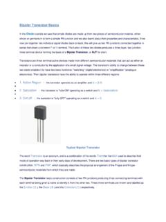
Bipolar Transistor BJT
sites.pitt.eduphase. It has a voltage gain that is always less than "1" (unity). The load resistance of the common collector transistor receives both the base and collector currents giving a large current gain (as with the common emitter configuration) therefore, providing good current amplification with very little voltage gain.

Low Noise, Precision Operational Amplifier Data Sheet OP27
www.analog.comfrequency of 2.7 Hz, and high gain (1.8 million), allow accurate high-gain amplification of low-level signals. A gain bandwidth product of 8 MHz and a 2.8 V/µs slew rate provide excellent dynamic accuracy in high speed, data-acquisition systems. A low input bias current of ±10 nA is achieved by use of a bias current cancellation circuit.
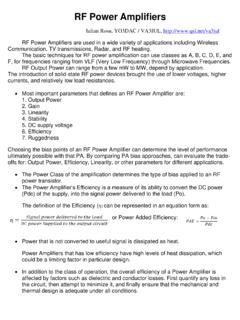
RF Power Amplifiers - QSL.net
www.qsl.netamplifiers, or the simple high impedance voltage bias used in FET PA’s. • Running the Power Amplifier in a mid-AB class condition the power gain may be 3dB higher than Class-B.

MOSFET AMPLIFIER - Learn LTSpice: A Tutorial
learn-ltspice.weebly.comLet us consider, we are using 5V supply voltage (V1). We are going to use this circuit diagram. First we have to choose the Value of R3. Let us consider V D =2.5 V, to get the maximum output swing. So, voltage drop across R3 = V1-2.5 V = 2.5V. Current Id should be less than that can be handled by the MOSFET. Let us consider the value of R3=100 Ohm.

931 Signal Conditioners - Rockwell Automation
literature.rockwellautomation.comseperately wire devices to the power supply. And the space-saving 931 Nano versions are only 6 mm wide. Critical process measurements such as temperature, pressure, flow, level, weight, speed, frequency, current or voltage in your continuous or batch production process are exposed to noise and harsh environmental

THE 37 SENSOR KIT TUTORIAL
images-eu.ssl-images-amazon.compositive pulse current 0.3~1A, reverse voltage 5V, dissipation power 90mW, working temperature range -25~+80℃, and storage temperature range between 40~100℃, the welding temperature 260 ℃) infrared tube with a closed head should be matching use,