Example: stock market
Chapter 9 Sinusoidal Steady–State Analysis
It remains sinusoidal of the same frequency as the driving source if the circuit is linear (with constant R, L, C values). 2. The amplitude differs from that of the source. 3. The phase angle differs from that of the source. 10. ... eliminate dc signals. ...
Tags:
Information
Domain:
Source:
Link to this page:
Documents from same domain

電力電子元件簡介 - 清華大學電機系-NTHUEE
www.ee.nthu.edu.twPage 3 功功率半率半導導體元件體元件之之控制控制特性特性 (1) Uncontrolled turn-on and off: (diode) (2) Controlled turn-on and uncontrolled turn-off: (SCR)

切換式(開關式)磁阻馬達之驅動 控制與應岦
www.ee.nthu.edu.tw2 3 3 AC source +-Inverter Vdc AC motor VVVF 3 voltage Rectifier or SMR φ φ EC Load Switching control Command Controller Current feedback Velocity and/or position feedback

띌뒹ꓹ꒧껈---- - ee.nthu.edu.tw
www.ee.nthu.edu.twOutlines • 륱ꑬ꒸ꗳ꙰꛳ꑵꝀ? • ꒰믲걏ꕢ뻉엩? • PN곉궱 • CMOS꒸ꗳ슲꒶ • ꕢ뻉엩뭳땻슲꒶ • ꣤ꕌꖼ꣓ꪺ땯깩 • 뙩ꑊꕢ뻉엩믢냬삳ꚳ꒰믲럇돆?
Chapter 8 Natural and Step Responses of RLC Circuits
www.ee.nthu.edu.tw1 Chapter 8 Natural and Step Responses of RLC Circuits 8.1-2 The Natural Response of a Parallel RLC Circuit. 8.3 The Step Response of a Parallel . RLC . Circuit
Chapter 13 The Laplace Transform in Circuit Analysis
www.ee.nthu.edu.tw1. Chapter 13 The Laplace Transform in Circuit Analysis. 13.1 Circuit Elements in the s Domain. 13.2-3 Circuit Analysis in the s Domain. 13.4-5 The Transfer Function and Natural Response
電力電子元件簡介 - ee.nthu.edu.tw
www.ee.nthu.edu.twPage 2 常用功率半導體元件之額定(表二) Voltage/current ratings Switching frequency (speed) Switching time On-state resistance (or on-state voltage/current)

Lecture 8: Mechanical Vibration
www.ee.nthu.edu.tw1 ENE 5400 , Spring 2004 1 Lecture 8: Mechanical Vibration Discrete systems Energy method Lumped-parameter analysis »1 d.o.f. »Multi-d.o.f. (Eigenvalue analysis)
Chapter 18 Two-Port Circuits
www.ee.nthu.edu.tw1. Chapter 18 Two-Port Circuits. 18.1 The Terminal Equations. 18.2 The Two-Port Parameters. 18.3 Analysis of the Terminated Two-Port Circuit . 18.4 Interconnected Two-Port Circuits
Chapter 11 Balanced Three-Phase Circuits
www.ee.nthu.edu.twWhy a balanced three-phase circuit can be analyzed by an equivalent one-phase circuit? How to get all the unknowns (e.g. line voltage of the load) by the result of one-phase circuit analysis? Why the total instantaneous power of a balanced three-phase circuit is a constant?

Chapter 7 Response of First-order RL and RC Circuits
www.ee.nthu.edu.twCircuit model of a discharging RC circuit Consider the following circuit model: For t <0, C is open and biased by a voltage V g, while R 1 and R carry no current. For t >0, the capacitor voltage decreases and the energy is dissipated via R.
Related documents
Lecture 2: Signals and systems: part I - MIT OpenCourseWare
ocw.mit.eduSinusoidal signals for both continuous time and discrete time will be-come important building blocks for more general signals, and the representa-tion using sinusoidal signals will lead to a very powerful set of ideas for repre-senting signals and for analyzing an important class of systems. We consider a
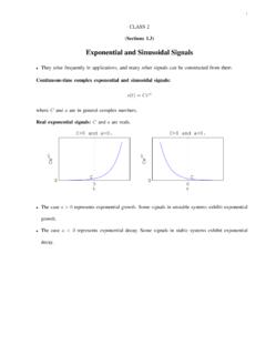
Sections 1.3 0 Exponential and Sinusoidal Signals
www2.hawaii.eduSinusoidal signals: Acos(w0t+`) and Asin(w0t+`): where A is real, w0 is real, ` is real, and t is the time. (Graph one of the signals!) † They arise in systems that conserve energy such as an ideal LC circuit or an ideal mass-spring system. † – Periodic with the same fundamental period T0 = 2…=jw0j – jw0j is the fundamental frequency ...
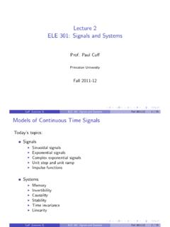
Lecture 2 Models of Continuous Time Signals
www.princeton.eduSinusoidal Signals A sinusoidal signal is of the form x(t) = cos(!t + ): where the radian frequency is !, which has the units of radians/s. Also very commonly written as x(t) = Acos(2ˇft + ): where f is the frequency in Hertz. We will often refer to !as the frequency, but it must be kept in mind

CIRCUITS LABORATORY EXPERIMENT 3 AC Circuit Analysis
classes.engineering.wustl.edu(1) Determine the steady-state behavior of linear circuits driven by sinusoidal sources, (2) Use the oscilloscope to measure the phase difference between two sinusoidal signals, (3) Determine analytically the frequency response of a network, (4) Construct Bode plots relating the magnitude and phase response of the voltage

SIGNALS AND SYSTEMS - gvpcew.ac.in
gvpcew.ac.inExponential and Sinusoidal Signals: Exponential and sinusoidal signals are characteristic of real-world signals and also from a basis (a building block) for other signals. A generic complex exponential signal is of the form: where C and a are, in general, complex numbers. Lets investigate some special cases of this signal

SINUSOIDAL SIGNALS - Åbo Akademi
users.abo.fiWHY SINUSOIDAL SIGNALS? † Physical reasons: - harmonic oscillators generate sinusoids, e.g., vibrating structures - waves consist of sinusoidals, e.g., acoustic waves or electromagnetic waves used in wireless transmission † Psychophysical reason: - speech consists of superposition of sinusoids - human ear detects frequencies