Transcription of CHARGING SYSTEMS - Autoshop 101
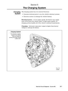
1 GeneralThe CHARGING system converts mechanical energy into electrical energy when the engine is running. This energy is needed to operate the loads in the vehicle's electrical system. When the CHARGING system's output is greater than that needed by the vehicle, it sends current into the battery to maintain the battery's state of charge. Proper diagnosis of CHARGING system problems requires a thorough understanding of the system components and their operation. OperationWhen the engine is running, battery power energizes the CHARGING system and engine power drives it.
2 The CHARGING system then generates electricity for the vehicle's electrical SYSTEMS . At low speeds with some electrical loads "on" ( , lights and window defogger), some battery current may still be needed. But, at high speeds, the CHARGING system supplies all the current needed by the vehicle. Once those needs are taken care of, the CHARGING system then sends current into the battery to restore its charge. CHARGING SYSTEMS Page 1 Toyota Motor Sales, , Inc.
3 All Rights Reserved. Toyota CHARGING SystemsTypical CHARGING system components include: IGNITION SWITCH When the ignition switch is in the ON position, battery current energizes the alternator. ALTERNATORM echanical energy is transferred from the engine to the alternator by a grooved drive belt on a pulley arrangement. Through electromagnetic induction, the alternator changes this mechanical energy into electrical energy. The alternating current generated is converted into direct current by the rectifier, a set of diodes which allow current to pass in only one direction.
4 VOLTAGE REGULATOR Without a regulator, the alternator will always operate at its highest output. This may damage certain components and overcharge the battery. The regulator controls the alternator output to prevent overcharging or undercharging. On older models, this is a separate electromechanical component which uses a coil and contact points to open and close the circuit to the alternator. On most models today, this is a built-in electronic device. BATTERYThe battery supplies current to energize the alternator.
5 During CHARGING , the battery changes electrical energy from the alternator into chemical energy. The battery's active materials are restored. The battery also acts as a "shock absorber" or voltage stabilizer in the system to prevent damage to sensitive components in the vehicle's electrical system. INDICATORThe CHARGING indicator device most commonly used on Toyotas is a simple ON/OFF warning lamp. It is normally off. It lights when the ignition is turned "on" for a check of the lamp circuit . And, it lights when the engine is running if the CHARGING system is undercharging.
6 A voltmeter is used on current Supra and Celica models to indicate system voltage .. it is connected in parallel with the battery. An ammeter in series with the battery was used on older Toyotas. FUSINGA fusible link as well as separate fuses are used to protectcircuits in the CHARGING SYSTEMS Page 2 Toyota Motor Sales, , Inc. All Rights Reserved. Alternator ConstructionGENERALTwo different types of alternators are used on Toyota vehicles.
7 A conventional alternator and separate voltage regulator were used on all Toyotas prior to 1979. A new compact, high-speed alternator with a built-in IC regulator is now used on most models. Both types of alternators are rated according to current output. Typical ratings range from 40 amps to 80 amps. CONVENTIONAL ALTERNATOR This type of alternator is currently used on some 1986 Tercel models, and all Toyotas prior to 1979. CHARGING SYSTEMS Page 3 Toyota Motor Sales, , Inc.
8 All Rights Reserved. TOYOTA COMPACT, HIGH-SPEED ALTERNATOR Beginning with the 1983 Camry, a compact, high-speed alternator with a built-in IC regulator is used on Toyota vehicles. Corolla models with the 4A-C engine use a different alternator with an integral IC regulator. This new alternator is compact and lightweight. It provides better performance, as well as improved warning functions. If either the regulator sensor (terminal "S") or the alternator output (terminal "B") become disconnected, the warning lamp goes on.
9 It also provides better serviceability. The rectifier, brush holder, and IC regulator are bolted onto the end frame. CHARGING SYSTEMS Page 4 Toyota Motor Sales, , Inc. All Rights Reserved. Alternator TerminalsToyota's high-speed alternator has the following terminals: "B", "IG", "S", "U', and "17". When the ignition switch is "on," battery current is supplied to the regulator through a wire connected between the switch and terminal "IG".
10 When the alternator is CHARGING , the CHARGING current flows through a large wire connected between terminal "B" and the battery. At the same time, battery voltage is monitored for the MIC regulator through terminal "S". The regulator will increase or decrease rotor field strength as needed. The indicator lamp circuit is connected through terminal "U'. If there is no output, the lamp will be lit. The rotor field coil is connected to terminal "P, which is accessible for testing purposes through a hole in the alternator end frame.