Transcription of Chemical Analysis Group Agilent 6890 Gas Chromatograph
1 Chemical Analysis GroupAgilent 6890 Gas Chromatograph6890 Site Prep and InstallationDocument A15283 Site Preparation andInstallation ManualHP 6890 SeriesGas ChromatographLittle Falls OperationHewlett-Packard Company2850 Centerville RoadWilmington, DE 1996 All Rights , adaptation,or translation withoutpermission is prohibited,except as allowed underthe copyright part numberG1530-90300 First Edition, Nov 1994 Second Edition, Oct 1996 Printed in USAW arrantyThe information containedin this document is subjectto change without makes nowarranty of any kind withregard to this material,including, but not limitedto, the implied warrantiesof merchantability andfitness for a particularpurpose. Hewlett-Packardshall not be liable for errorscontained herein or forincidental or consequentialdamages in connection withthe furnishing,performance, or use of InformationThe HP 6890 GasChromatograph meets thefollowing IEC(InternationalElectrotechnicalCommiss ion) classifications:Safety Class 1, TransientOvervoltage Category II,and Pollution Degree unit has beendesigned and tested inaccordance with recognizedsafety standards anddesigned for use indoors.
2 Ifthe instrument is used in amanner not specified by themanufacturer, theprotection provided by theinstrument may beimpaired. Whenever thesafety protection of the HP6890 has beencompromised, disconnectthe unit from all powersources and secure the unitagainst servicing to qualifiedservice parts orperforming anyunauthorized modificationto the instrument mayresult in a safety the AC powercord before removingcovers. The customershould not attempt toreplace the battery or fusesin this instrument. Thebattery contained in thisinstrument is SymbolsWarnings in the manual oron the instrument must beobserved during all phasesof operation, service, andrepair of this to comply withthese precautions violatessafety standards of designand the intended use of Companyassumes no liability for thecustomer s failure tocomply with warning calls attentionto a condition or possiblesituation that could causeinjury to the caution calls attention toa condition or possiblesituation that coulddamage or destroy theproduct or the user s accompanyinginstructions formore a earth(ground) radio-activity UserInformation for In VitroDiagnostic ApplicationsThis is a multipurposeproduct that may be usedfor qualitative orquantitative analyses inmany applications.
3 If usedin conjunction with provenprocedures (methodology)by qualified operator, oneof these applications maybe In Vitro instrumentperformance characteristicsand instructions areincluded in this In Vitro Diagnosticprocedures andmethodology remain thechoice and theresponsibility of the user,and are not EmissionCertification for FederalRepublic of GermanySound pressure Lp< 65 dB(A)During normal operationAt the operator positionAccording to ISO 7779(Type Test)When operating the HP6890 with cryo valveoption, the sound dB(A) during cryovalve operation for shortburst LP< 65 dB(A)Am ArbeitsplatzNormaler BetriebNach DIN 45635 T. 19(Typpr fung)Bei Betrieb des HP 6890mit Cryo Ventil Optiontreten beim Oeffnen desVentils impulsfoermigSchalldrucke Lp bis dB(A) 1. Site PreparationTemperature and humidity oven toxic or noxious space for packed for capillary gas tubing for carrier and detector pressure regulatorgas supply tubing cooling a carbon liquid valve actuator 2.
4 InstallationStep 1. Unpacking the 2. Placing the GC system on the 3. Turning the power 4. Connecting tubing to the gas supply 5. Attaching traps to the gas supply 6. Attaching a SWAGELOK tee to 7. Attaching tubing to the inlet 8. Attaching tubing to detector 9. Checking for 10. Attaching cryogenic liquid 11. Attaching valve actuator 12. Setting source 13. Connecting cable, general start/stop decimal event 14. Setting the GC Automatic Liquid Sampler 15. Configuring the for the HP for the HP INET for remote Making SWAGELOK PreparationHow to prepare your laboratory forinstallation and use of the and humidity ranges, 3 Ventilation requirements, 4 Benchtop space requirements, 5 Electrical requirements, 8 Gas requirements, 10 Gases for packed columns, 10 Gases for capillary columns, 11 Gas purity, 12 The gas plumbing, 13 Supply tubing for carrier and detector gases, 14 Two-stage pressure regulators, 15 Traps, 16 Cryogenic cooling requirements, 17 Choosing a coolant, 17 Using carbon dioxide, 18 Using liquid nitrogen, 20 Supplying valve actuator air, 212 Site preparation at a glanceBefore the GC arrives, make sure yourlaboratory meets the following environ-mental, weight, power, and gas require-ments.
5 You should also refer to thischecklist forsupplies that you need to operate yourGC, such as traps and tubing. You canfind more site preparation information inthis Preparation Checklist The site is well ventilated and free of corrosive materials and overhanging obstacles. Site temperature is within the recommended range of 20 to 27EC. Site humidity is within the recommended range of 50 to 60%. Bench space is adequate for the GC with EPC: 50 cm x cm x 50 cm (21 in. x 23 in. x 21 in.)Bench space is adequate for the GC without EPC: 50 cm x 68 cm x 50 cm (21 in. x in. x 21 in.) Bench can support the weight of the HP 6890 system. Power receptacle is earth grounded. Electrical supply meets allGC s power requirements; see page 10. Voltage supply is adequate for oven oven:2,250 oven:2,950 VA. Gas supplies meet the requirements of your columns and detectors; see page 12. Gases meet purity requirements. All should be chromatographic-grade pure or should be zero-grade or better.
6 Obtained precleaned, 1/8-inch copper tubing for inlet and detector gas supplies: Inlet and detector gas supplies have two-stage pressure regulators installed (optional). Obtained traps for inlet and detector gas supplies molecular sieve trap, hydrocarbon trap, and/or oxygentrap. Obtained liquid N2or liquid CO2(depending on requirements) for cryogenic cooling. Obtained 1/4-inch insulated copper tubing for liquid N2suppliesOR1/8-inch heavy-walled, stainless steeltubing for liquid CO2supplies. Obtained insulation for liquid N2tubing. Obtained air for valve PreparationSite preparation involves two general steps: insuring that yourlaboratory is capable of supporting the operation of the GC and obtainingsupplies and tools you will need to install the instrument. A list of thenecessary tools and supplies appears at the beginning of the Installation chapter. Most supplies are available fromHewlett-Packard. See the HP Analytical Direct Analytical Columns andSupplies catalog for descriptions and ordering information.
7 You canobtain a copy of the catalog from your local sales and humidity rangesOperating the GC within the recommended ranges insures optimuminstrument performance and temperaturerangeTemperature range20 to 27EC5 to 40 ECRecommended humidity rangeHumidity range50 to 60%Up to 31EC, 5 to 80%At 40EC, 5 to 50%Recommended altitude rangeUp to 2000 mAfter exposing the GC to extremes of temperature or humidity, allow 15minutes for it to return to the recommended Preparation4 Ventilation requirementsThe GC is cooled by convection: air enters vents in the side panels andunderneath the instrument. Warmed air exits through slots in the top,rear, and side panels. Do not obstruct air flow around the proper cooling and general safety, always operate the instrumentwith cover panels properly oven exhaustHot air (up to 450EC) from the oven exits through a vent in the at least 20 cm (10 in.) clearance behind the instrument todissipate this not place temperature-sensitive items (for example, gas cylinders,chemicals, or regulators) in the path of the heated exhaust.
8 Be carefulwhen working behind the instrument during cool-down cycles to avoidburns from the hot space is limited, the Oven Exhaust Deflector (HP part ) may improve oven cooling. It diverts exhaust air up andaway from the instrument. You can connect it to a (4-in.)exhaust-duct system, route the exhaust to a fume hood, or vent theexhaust outside the building with diameter (4-inch diameter)furnace toxic or noxious gasesDuring normal operation of the GC with many detectors and inlets, someof the carrier gas and sample vents outside the instrument. If anysample components are toxic or noxious, or if hydrogen is used as thecarrier gas, the exhaust must be vented to a fume hood. Place the GC inthe hood or attach a large diameter venting tube to the outlet for further prevent contamination from noxious gases, you can attach achemical trap to the split Preparation5 Benchtop space requirementsThe GC with electronic pneumatics control (EPC) is 59 cm (23 in.)
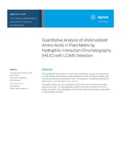
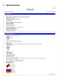
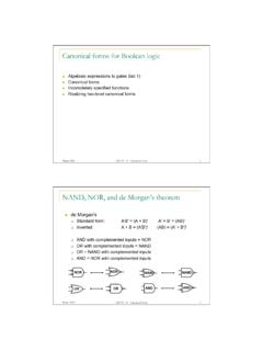
9 NonEPC model is 68 cm ( in.) wide. Both are 50 cm (21 in.) highand 50 cm (21 in.) area above the GC should be clear, with no shelves or overhangingobstructions that limit access to the top of the instrument and interferewith cooling. You may need additional space for other instruments usedwith your GC. Figure 1 shows some common system 1 presents the dimensions, voltage requirements, heat production,and weight of the GC and other Hewlett-Packard instruments often usedwith it. Use this table to insure that you have adequate space and powerfor the entire system. Allow at least cm (4 in.) space betweeninstruments for Preparation6 Figure 1. Common GC SystemConfigurations Top ViewsGC with HP 5972A Mass Selective DetectorGC59* cm50 cmGC with HP ChemStationGC59* cm50 cmHP cmLaserJet cmMouse pad28 cm23 cmMSD65 cm17 cmGC with HP Automatic Liquid SamplerGC59* cm50 cmInjector 44 cmabove GCTray cmleft of GCALS Controller10 cm31 cm*68 cm for non-EPC Preparation7 Table 1.
10 Dimensions, Power, Heat Production, and WeightInstrumentHeight WidthDepthPower(VA)HeatWeightHP 6890 Gas Chromato-graphEPC version50 cm21 cm23 cm21 ,2508,100 KJoules7,681 Btu/hr50 kg110 lbNon-EPC version50 cm20 in50 cm21 ,2508,100 KJoules7,681 kg125 lbFast heating oven,same for EPC and non-EPC 2,95010,620 KJoules10,071 Btu/hr GC Automatic Liquid Sam-plerG 1512A Controller10 cm4 cm13 cm12 KJoules515 lb18593 Injector44 cm above GC17 in. above GC18596 cm left of GC9 in. left of GCComputer*Computer with monitor21 5972A Mass SelectiveDetector35 ,158 Btu/hr,3,000 with lbHP 7694 Headspace Sampler31 cm16 cm22 cm22 ,215 KJoules2,100 lbPrintersLaserJet Series 4 Plus30 lbIntegratorsHP 3396 Series III Integrator,HP 3395 Integrator13 cm18 cm18 KJoule120 lbHP 35900C/D/E Analog-to-Digital Converter104 cm4 cm13 cm11 KJoules205 lb* General specificationsfor a mid-size, desktop Preparation8 Electrical requirementsGroundingA proper earth ground is required for GC protect users, the metal instrument panels and cabinet are groundedthrough the three-conductor power line cord in accordance withInternational Electrotechnical Commission (IEC) three-conductor power line cord, when plugged into a properlygrounded receptacle, grounds the instrument and minimizes shockhazard.