Example: stock market
Number Representation and Computer Arithmetic
One way to encode decimal digits using binary signals is to encode each of the digits 0-9 by means of its 4-bit binary representation. The resulting binary-coded decimal (BCD) representation is shown below:
Tags:
Information
Domain:
Source:
Link to this page:
Documents from same domain
Transistor Technologies for High Efficiency and Linearity
web.ece.ucsb.eduDifferential Topology • Double the available voltage swing • Even-order harmonic suppression • Double the frequency of current injection into substrate –Reduce the potential for LO-pulling • The tail current source is removed from the standard differential pair (this is a “quasi-differential” structure) –DC current set by the biasing of input devices

Phase Locked Loop Circuits
web.ece.ucsb.eduClock generation: B. Razavi, Design of Analog CMOS Integrated Circuits, Chap. 15, McGraw-Hill, 2001. 1. Definition. A PLL is a feedback system that includes a VCO, phase detector, and low pass filter within its loop. Its purpose is to force the VCO to replicate and track the frequency and phase at the input when in lock.

ADS Tutorial Stability and Gain Circles ECE145A/218A
web.ece.ucsb.eduequations. The syntax is: gp_circle(S, gain, # points on circle) where S is the S-parameter matrix. Let’s illustrate. In the example below, a table is used to display frequency, maximum stable gain (MSG), the stability factor, k, and the magnitude of delta. The gain circles are at MSG (MaxGain1 in this case), and 1 and 2 dB below MSG.

Audio Amplifier Circuit - UC Santa Barbara
web.ece.ucsb.eduWeek #1: Audio amplifier Week #2: Microphone circuit The audio amplifier project is more difficult and time-consuming than the microphone pre-amp, so part of week #2 may be used to finish the audio amp. All breadboarding and testing can and should be done in lab. Soldering and hardwiring can and should be done outside lab.

Harmonic Balance Simulation on ADS
web.ece.ucsb.eduHarmonic Balance Simulation on ADS General Description of Harmonic Balance in Agilent ADS 1 Harmonic balance is a frequency-domain analysis technique for simulating nonlinear circuits and systems. It is well-suited for simulating analog RF and microwave circuits, ... function is driven to a given small value), then the resulting voltage ...

Quality factor, Q
web.ece.ucsb.eduWhen a resonant circuit is connected to the outside world, its total losses (let’s call them RP or GP) are combined with the source and load resistances, RS and RL. For example, Here is a parallel resonant circuit (C,L and RP)connected to the outside. The total Q of this circuit is called the loaded Q or QL and is given by

Latches, the D Flip-Flop & Counter Design
web.ece.ucsb.eduFebruary 6, 2012 ECE 152A - Digital Design Principles 2 Reading Assignment Brown and Vranesic 7Flip-Flops, Registers, Counters and a Simple Processor 7.1 Basic Latch 7.2 Gated SR Latch 7.2.1 Gated SR Latch with NAND Gates 7.3 Gated D …

Flip-Flops and Sequential Circuit Design
web.ece.ucsb.edu11 Latches and Flip-Flops 11.5 S-R Flip-Flop 11.6 J-K Flip-Flop 11.7 T Flip-Flop 11.8 Flip-Flops with Additional Inputs 11.9 Summary 12 Registers and Counters 12.5 Counter Design Using S-R and J-K Flip-Flops 12.6 Derivation of Flip-Flop Input Equations – Summary

BASICS OF THE SPECTRUM ANALYZER - UC Santa Barbara
web.ece.ucsb.eduFourier ⋅ π → − + + Now instead of a bank of narrow filters, we shall have one narrow filter centered at a fixed frequency, say fI, and we shall scan the signal spectrum across this filter by multiplying x(t) by a sinusoid of varying frequency f0. See Figure 1. …

Mealy and Moore Machines
web.ece.ucsb.eduFebruary 22, 2012 ECE 152A - Digital Design Principles 5 Finite State Machines Two types (or models) of sequential circuits (or finite state machines) Mealy machine Output is function of present state and present input Moore machine Output is function of present state only Analysis first, then proceed to the design of
Related documents

PCF8523 Real-Time Clock (RTC) and calendar
www.nxp.comcoded in Binary Coded Decimal (BCD) format. Other registers are either bit-wise or standard binary. When one of the RTC registers is read, the contents of all counters are frozen. Therefore, faulty reading of the clock and calendar during a carry condition is prevented. The PCF8523 has a battery backup input pin and battery switch-over circuit.
Basics of PLCs - Diagramasde.com
diagramas.diagramasde.comBCD Binary-Coded Decimal (BCD) are decimal numbers where each digit is represented by a four-bit binary number. BCD is commonly used with input and output devices. A thumbwheel switch is one example of an input device that uses BCD. The binary numbers are broken into groups of four bits, each group representing a decimal equivalent.
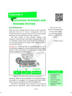
Encoding Schemes and Number System
ncert.nic.inthe encoded value into binary values which can be understood by a computer. Table 2.1 ASCII code for some printable characters Character Decimal Value Character Decimal Value Character Decimal Value Space 32 @ 64 ` 96! 33 A 65 a 97 ” 34 B 66 b 98 # 35 C 67 c 99 $ 36 D 68 d 100 % 37 E 69 e 101 & 38 F 70 f 102 ‘ 39 G 71 g 103 ( 40 H 72 h 104

User´s Guide: BNI EIP-502-105-Z015 / BNI EIP-508-105-Z015 …
assets.balluff.comDecimal numbers are shown without additional information (e.g. 123), Hexadecimal numbers are shown with the additional indicator hex (e.g., 00 hex ... A-coded (8x female) Dimensions (W x H x D in mm) 68 x 224 x 37.9 Type of mounting Screw mounting with 2 …
CHAPTER 2 Data Representation in Computer Systems
www2.southeastern.eduIf the 4-bit binary value 1101 is unsigned, then it represents the decimal value 13, but as a signed two’s complement number, it represents -3. • C programming language has and unsigned intint as possible types for integer variables. • If we are using 4-bit unsigned binary numbers and we add 1 to 1111, we get 0000 (“return to zero”). •
User´s Guide: BNI USB-901-013-A501 EN - Balluff
assets.balluff.comBalluff Network Interface USB IO-Link Master, BNI USB-901-000-A501 . www.balluff.com 2 1 Notes for the user 1.1 About this guide This guide describes the Balluff USB IO-Link Master module, which allows you to connect IO-Link devices to the PC, as well as installation of the associated software.
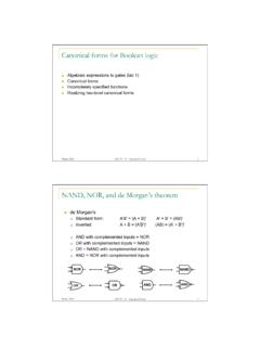
Canonical forms for Boolean logic - University of Washington
courses.cs.washington.eduWinter 2010 CSE370 - IV - Canonical Forms 7 Regular logic Need to make design faster Need to make engineering changes easier to make Simpler for designers to understand and map to functionality harder to think in terms of specific gates easier to think in terms of larger multi-purpose blocks Winter 2010 CSE370 - IV - Canonical Forms 8

Chemical Analysis Group Agilent 6890 Gas Chromatograph
www.agilent.comChemical Analysis Group Agilent 6890 Gas Chromatograph 6890 Site Prep and Installation Document A15283