Transcription of Chevy Equinox 2010-2015 / GMC Terrain 2010-2014 …
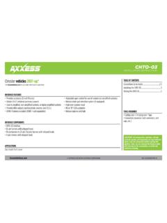
1 REV. 1/26/2017 INST99-3307 GINSTALLATION INSTRUCTIONS FOR PART 99-3307 GMETRA. The World s best kits. COPYRIGHT 2017 METRA ELECTRONICS CORPORATION CAUTION! All accessories, switches, climate controls panels, and especially air bag indicator lights must be connected before cycling the ignition. Also, do not remove the factory radio with the key in the on position, or while the vehicle is running. ISO DIN radio provision with pocket ISO DDIN radio provision Painted gray to match factory finish A) Radio trim panel B) Radio brackets C) Pocket D) (6) #8 x 3/8 Phillips screws E) (2) #10 x Phillips screws F) (2) #10 panel clips G) Axxess interface and wiring harness (not shown)KIT FEATURESKIT COMPONENTSWIRING & ANTENNA CONNECTIONS (sold separately)Wiring Harness: Axxess interface and harness includedAntenna Adapter.
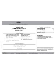
2 40-EU55 Panel removal tool Phillips screwdriver 9/32 socket wrenchTOOLS REQUIREDC hevy Equinox 2010 - 2015 / GMC Terrain 2010 - 2014 (with monochrome display)99-3307 GATable of ContentsBCEFDDash Disassembly ..2 Kit Preparation ..3 Kit Assembly ISO DIN radio provision with pocket ..4 ISO DDIN radio provision ..4 Axxess Interface Installation ..5-799-3307G2 Dash Disassembly1. With pocket above factory radio controls - Remove (2) 9/32 screws from inside the pocket, then unclip and remove the pocket. 2. Without pocket, just unsnap and remove the panel.
3 (Figure A)3. Unsnap, unplug, and remove the radio/ climate control panel. (Figure B)4. Unclip and remove the (2) side panels from the left and right side of the pocket/CD slot panel. (Figure C)5. Remove (4) 9/32 screws to remove the pocket/CD slot panel. Remove the power outlet and attach it to the included pocket if installing single DIN. If you are mounting a DDIN the power outlet will not be retained with this kit. Remove the rubber bottom from the factory pocket and save it for final assembly. (Figure D) 6. Remove (2) 9/32 screws from each a/c vent then unclip and remove the vents.
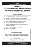
4 Remove the screws inside and under the vent cavities and two from below the vent locations. (this will allow flex in the dash to fit the aftermarket in later). (Figure E)7. Remove (4) 9/32 screws securing the radio chassis and remove. (Figure F) Continue to Kit Preparation(Figure A)(Figure D)(Figure C)(Figure F)(Figure B)(Figure E)99-3307G(Figure A)(Figure B)3 Kit Preparation1. A small section of the sub-dash must be cut with a cutting tool to allow the radio to fit: a. Remove the lip from the section of dash just above the original CD slot location by cutting along the dotted line.
5 (Upper shading in figure A) b. It is also recommended that a portion of the sub dash in front side of the console be removed. (Lower shading in figure A)2. Attach the (2) #10 panel clips included with the kit onto the front legs of the radio brackets. (Figure B)Continue to Kit Assembly99-3307G4 Kit AssemblyISO DDIN radio provision1. Attach the radio brackets to the radio using the screws supplied with the radio. (Figure A) Continue to Axxess Interface Installation(Figure B)(Figure A)ISO DIN radio provision with pocket1.
6 Attach the pocket to the radio brackets using the (4) #8 x 3/8 Phillips screws provided. (Figure A)2. Remove the metal DIN sleeve and trim ring from the aftermarket Slide the radio into the bracket/pocket assembly and then secure it using the screws supplied with the radio. (Figure B) Continue to Axxess Interface Installation (Figure A)99-3307G5 Axxess Interface Installation Provides accessory power (12-volt 10-amp) Retains (retained accessory power) Can be used in amplified or non-amplified models Provides NAV outputs (mute, parking brake, reverse, and ) Pre-wired ASWC-1 harness included (ASWC-1 sold separately) Retains balance and fade Micro B USB updatableINTERFACE FEATURES Wire cutter Crimp tool Solder gun Tape Small flat-blade screwdriver Connectors (example.)
7 Butt-connectors, bell caps, etc.)TOOLS REQUIRED Axxess Interface 3307 harnessINTERFACE COMPONENTSFrom the 3307 harness to the aftermarket radio: Connect the Black wire with a ring terminal to the chassis of the aftermarket radio. Attention: The interface will not function properly unless this step is performed exactly as stated. Connect the Black wire to the ground wire. Connect the Yellow wire to the battery wire. Connect the Red wire to the accessory wire. If the vehicle is factory amplified, connect the Blue/White wire to the amp turn on wire.
8 This wire must be connected to hear sound from the factory amplifier. If the aftermarket radio has an illumination wire, connect the Orange/White wire to it. If the aftermarket radio has a mute wire, connect the Brown wire to it. If the mute wire is not connected, the radio will turn off when OnStar is activated. Connect the Gray wire to the right front positive speaker output. Connect the Gray/Black wire to the right front negative speaker output. Connect the White wire to the left front positive speaker output. Connect the White/Black wire to the left front negative speaker output.
9 Connect the Green wire to the left rear positive speaker output. Connect the Green/Black wire to the left rear negative speaker output. Connect the Purple wire to the right rear positive speaker output. Connect the Purple/Black wire to the right rear negative speaker output. Continued on the next pageConnections to be made99-3307G6 Connections to be made (cont.)Final AssemblyThe following (3) wires are only for multimedia/navigation radios that require these wires. Connect the Blue/Pink wire to the VSS/speed sense wire.
10 Connect the Green/Purple wire to the reverse wire. Connect the Light Green wire to the parking brake wire. The Black/Yellow wire is used for OnStar level adjustment for models that do not come equipped with steering wheel controls. See the OnStar Level Adjustment section for further instructions. Tape off and disregard the Green/Orange wire, it will not be used in this application If retaining the factory AUX-IN jack, connect the Red & White RCA jacks to the AUX pre-wired ASWC-1 harness: This harness is to be used along with the optional ASWC-1 (not included) to retain steering wheel audio controls.