Transcription of Choosing a Stencil - PhotoStencil | PhotoStencil Colorado
1 Choosing a Stencil Is a Stencil a commodity or a precision tool? A commodity is something that can be purchased from many suppliers, with the expectation that the performance will be the same. A precision tool is designed to perform a specific task, which, In the case of Stencil printing, is to provide defect-free printing. This article examines how to choose a precision Stencil tool for printing. By William E. Coleman, and Michael R. Burgess In light of recent demanding requirements of lead-free printing and ultra-fine-pitch printing of devices such as microBGAs and 0201 chip components, a precision Stencil tool is required.
2 The function of a Stencil is to deposit solder paste, conductive polymer, glue, or flux onto a substrate. Generally, the substrate is a PCB, but a silicon wafer is also used for printing solder paste onto wafer pads for wafer bumping. Ball-placement tools - although not specifically considered stencils - fall into the Stencil domain. Instead of transferring paste through Stencil apertures, solder balls are positioned over a wafer or BGA substrate through Stencil apertures. For paste printing, the Stencil printing process can be divided into three categories: the aperture-fill process, the paste-transfer process, and the positional location of the deposited paste.
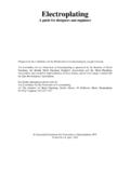
3 All three processes play a vital role in achieving the desired result - a precise volume of paste (a brick) deposited to the correct location on the substrate. Figure 1. Laser cut, no surface treatment, side wall. The first step in printing solder paste is to fill the Stencil aperture with paste. This is achieved using a metal squeegee blade. Several factors can contribute to the aperture-fill process. The orientation of the aperture with respect to the squeegee blade has an effect on the fill process. An aperture oriented with its long axis in the same direction as the blade stroke does not fill as well as an aperture oriented with its short axis to the blade stroke.
4 Squeegee speed also influences aperture fill. Squeegee speed must be reduced to fill the aperture with the long axis oriented parallel to the squeegee stroke. The squeegee-blade edge has an influence on how well the paste fills a Stencil aperture. The rule of thumb is to print at the minimum squeegee pressure while still maintaining a clean wipe of the solder paste on the Stencil surface. If squeegee pressure is too high, both the squeegee blade and the Stencil may be damaged. Excessive squeegee pressure can also cause paste smearing under the Stencil surface.
5 If the pressure is too low, one of two events may occur. Paste left on the squeegee side of a small aperture will hold the paste, preventing its release to the PCB pad, resulting in insufficient solder. Paste left on the squeegee side over large apertures will be pulled down through the aperture, resulting in excess solder. Proper squeegee pressure is the minimum pressure that achieves a clean wipe of the paste. Minimum pressure is a function of blade type. A recent study demonstrated that the minimum squeegee pressure for one squeegee blade* was about 40% of that of the teflon/nickel-coated blade for lead-free solder paste.
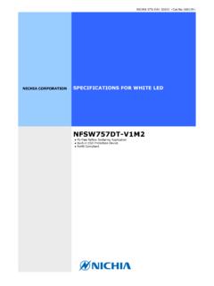
6 Tests have confirmed that lead-free solder pastes typically require about 25% more squeegee pressure than tin/lead pastes. Figure cut, electro polished side wall. There are two primary considerations for solder paste release: the area ratio/aspect ratio for Stencil design and the type of Stencil . The first is a function of Stencil design, while the second is a function of aperture-wall smoothness and side-wall geometry. The aspect ratio is the width of the aperture divided by Stencil thickness. It is generally accepted that an aspect ratio of or greater should achieve acceptable solder paste transfer.
7 The aspect ratio is a useful guide when the aperture length (L) is much larger than aperture width (W), such as greater than 5 the width. BGAs, microBGAs, and 0201s have aperture dimensions where L and W are close to the same value. These apertures are either circles and squares, or oblongs and squares with radius corners. In all cases, the length is much less than 5 the width. It is more common to use the area ratio as a guide to paste-transfer efficiency. The area ratio is the area beneath the Stencil aperture opening, divided by the area of the inside aperture wall.
8 For a rectangular aperture, the area ratio = [(L W)/2(L+W)T)], where L and W are the aperture length and width, respectively, and T is Stencil thickness. For a square aperture, area ratio = S/4T, where S is the side of the square. For a circular aperture, area ratio = D/4T, where D is the diameter of the circle. The generally accepted rule is to achieve area ratios of > for paste transfer. This was true until the advent of electroformed stencils. It is common with this technology to print apertures with area ratios down to One electroformed Stencil ** with relatively straight side walls and a smooth mirror-like finish promotes greater solder paste release, which is helpful as component sizes and pitches continue to decrease.
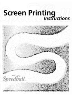
9 There are two primary Stencil technologies used within the industry: electroformed and laser-cut. Chemical etching can also be used to create steps for step stencils; however, final Stencil apertures are generally laser-cut. Three-dimensional (3-D) electroformed stencils are also available for use when unique steps are needed, providing release qualities required for fine-feature printing. Figure 3. Laser cut, electro polished, nickel plated side wall. Laser-cutting is a subtractive process. Traditional Gerber files are converted to CNC-type language files that the laser can interpret.
10 The final aperture shape and smoothness is impacted by a laser-cutting machine, cut speed, laser power, beam spot size, and beam focus. Some laser-cutting machines are homemade systems, some vintage lasers, and some are fine-cut laser machines. Electro-polishing and nickel-plating are also used to further smooth surface walls and improve solder paste release. Figures 1-3 demonstrate how successive surface treatment can smooth out the surface wall to improve paste release. As a minimum, a Stencil supplier should electro-polish the laser-cut stencils.