Transcription of CIC 1.SpectreRF Overview
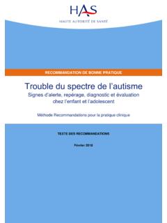
1 CIC. 1. SpectreRF Overview SpectreRF is an optional feature added to Spectre ,and is represented by 6 analyses: 1. PSS: Periodic Steady State Analysis 2. PAC: Periodic AC Analysis 3. PXF: Periodic Transfer Function Analysis 4. PNOISE: Periodic Noise Analysis Tdnoise: Time Domain Noise QPNOISE: Quasi-Periodic Noise (not discuss here). 5. PDISTO: Periodic Distortion Analysis QPSS: Quasi-Periodic Steady State (not discuss here). 6. Envelope Analysis (not discuss here). PAC, PXF, and PNOISE are similar in concept to AC, XF, and Noise.
2 However, they are applied to periodically-driven circuits such as mixers and oscillators. 1-1. CIC. SpectreRF in a Design Flow Design Schematic Analog Artist Environment Models The netlists include all components along with an analysis selection, simulation Netlist controls and statements to save, plot nodes or currents. SPECTRE Engine Spectre RF Control Analog Artist Plot Results Use Direct plot or the Calculator plot capabilities. 1-2. CIC. SpectreRF Tool Flow SpectreRF. No Stimuli is coperiodic PSS is a large-signal analysis Yes and determines the period of PDISTO Setup PSS setup the small-signal analyses.
3 PSS requires that multiple Spectre Engine Spectre Engine periodic stimuli be PDISTO Analysis PSS Analysis coperiodic. PDISTO Results PSS Results PDISTO is also a large- signal analysis, and need not Spectre Engine to be run after a PSS. -PAC Analysis analysis. PDISTO does not -PXF Analysis require multiple periodic -PNOISE Analysis stimuli to be coperiodic. Report Results 1-3. CIC. SpectreRF Features Compute a steady-state solution efficiently and directly Handles very large circuits (~ 10,000 transistors). Displays results in both time and frequency domains Use Discrete Fourier Transform (DFT) for better accuracy Displays standard RF measurements, such as s-parameter in Smith chart, NF, IP3, and 1dB compression point in the Analog Artist design environment.
4 Performs oscillator analysis. 1-4. CIC. 2. S-Parameter Analysis Linear Simulation: Entirely in the frequency domain A basic RF feature of the Spectre simulator Ports: Specify the port number on the psin ( or port); psin (or port). can act as a source port or a load. Required properties for linear analysis: Resistance & Port number Noise Analysis: Use Nfmin and NF for 2-port circuits ONLY. 2-1. CIC. Plotting S-Parameter Simulation Results SP, ZP, YP, HP s-, z-, y-, and h-parameters GD group delay VSWR Voltage Standing Wave Ratio NFmin minimum noise figure Gmin reflection coefficient associated with Nfmin(also known as min, opt, or on).
5 Rn noise sensitivity parameter rn normalized equiv. Noise resistance NF noise figure Kf & B1f stability terms GT transducer gain GA available gain, assuming conjugate matched output GP power gain, assuming conjugate matched input Gmax maximum available power gain Gmsg maximum stable power gain Gumx maximum unilateral power gain ZM impedance at port m NC noise circles GAC available gain circles GPC power gain circles LSB load stability circles SSB source stability circles 2-2. CIC. Lab1 : S-parameter Analysis Create a new library and a new schematic view.
6 Use library analogLib create instance from & tsmc25rf to draw library tsmc25rf . the scheme. After drawing, push Design Check and Save; then push Tools Analog Environment, and the window Affirma Analog Circuit Design Environment will appear. 2-3. CIC. Setup Design Environment(1). Push Setup Model Libraries then the window Model Library Setup . appears. Setup the model library as shown right. Then click OK. Push Setup . Simulator/Directory/Host to designate the project directory. The default project directory is ~/simulation . Use Browse to access to the model files 2-4.
7 CIC. Setup Design Environment(2). You can use either an absolute model path or a relative model path IF you use the absolute approach, the setup is as shown right-upper. To use a relative path ,push Setup Simulation Files ,than Setup . Model Libraries .The setup is as shown right. 2-5. CIC. Setup Design Environment(3). Push Analyses Choose then the window Choosing Analyses appears. Key in the values as right and push ok, then some information will appear in the Analyses . domain of the window Affirma Analog Circuit Design Environment.
8 Push Select button then Push Simulation Netlist and Run to run to select the port on the the simulation. The Netlist will be saved under schematic window a directory called ~/simulation. Netlist and Run 2-6. CIC. See the Results Use the Direct Plot tool to look the results. In the S-parameter Results window choose some parameters to see their results. 2-7. CIC. Some Results 2-8. CIC. Save the results to *.s2p Edit the S-Parameter Options, and enter the path to the output S-parameter file in the file field of the OUTPUT. PARAMETERS section and OK the S-Parameter Options form.
9 And Simulate again. Check if the file is created in the appointed directory. 2-9. CIC. S2P File 2-10. CIC. Simulation State Push Session Save State to save simulation states under a directory called ~/.artist_states. Designate a new directory with the Session . Options command in the simulation window. Push Session Save State to load saved states for a design. 2-11. CIC. Read the S2P file(1). Create a new schematic view. Use library analogLib . (n2port cell) to draw the scheme. Simulate if the results are the same as before. 2-12.
10 CIC. 3. Lab2: Swept DC Analysis Create a new schematic view and use library analogLib & tsmc25rf to draw the scheme.. After Check and Save ; then call the window Affirma Analog Circuit Design Environment . Setup up the Model Libraries. Push Variables Copy From Cellview, and the defined variables appear in the Design Variables section. Double click on the variable name or push Variables Edit, the window Editing Design Variables . appears. Key in the appropriate value for the variables. 3-1. CIC. Set up the Design Environment(1).