Transcription of Circuit Symbols of Electronic Components
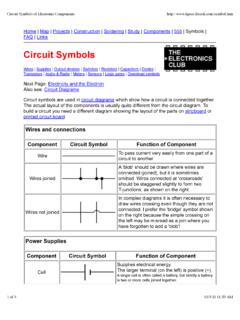
1 Home | Map | Projects | Construction | Soldering | Study | Components | 555 | Symbols |FAQ | LinksCircuit SymbolsWires | Supplies | Output devices | Switches | Resistors | Capacitors | Diodes |Transistors | Audio & Radio | Meters | Sensors | Logic gates | Download symbolsNext Page: Electricity and the ElectronAlso see: Circuit DiagramsCircuit Symbols are used in Circuit diagrams which show how a Circuit is connected actual layout of the Components is usually quite different from the Circuit diagram. Tobuild a Circuit you need a different diagram showing the layout of the parts on stripboard orprinted Circuit and connections Component Circuit Symbol Function of ComponentWireTo pass current very easily from one part of acircuit to joinedA 'blob' should be drawn where wires areconnected (joined), but it is sometimesomitted. Wires connected at 'crossroads'should be staggered slightly to form twoT-junctions, as shown on the not joinedIn complex diagrams it is often necessary todraw wires crossing even though they are notconnected.
2 I prefer the 'bridge' symbol shownon the right because the simple crossing onthe left may be misread as a join where youhave forgotten to add a 'blob'!Power Supplies Component Circuit Symbol Function of ComponentCellSupplies electrical larger terminal (on the left) is positive (+).A single cell is often called a battery, but strictly a batteryis two or more cells joined Symbols of Electronic of 910/3/11 11:53 AMBatterySupplies electrical energy. A battery is morethan one larger terminal (on the left) is positive (+).DC supplySupplies electrical = Direct Current, always flowing in supplySupplies electrical = Alternating Current, continually safety device which will 'blow' (melt) if thecurrent flowing through it exceeds a coils of wire linked by an iron are used to step up (increase)and step down (decrease) AC is transferred between the coils by themagnetic field in the core.
3 There is noelectrical connection between the (Ground)A connection to earth. For many electroniccircuits this is the 0V (zero volts) of the powersupply, but for mains electricity and someradio circuits it really means the earth. It isalso known as Devices: Lamps, Heater, Motor, etc. Component Circuit Symbol Function of ComponentLamp (lighting)A transducer which converts electrical energyto light. This symbol is used for a lampproviding illumination, for example a carheadlamp or torch (indicator)A transducer which converts electrical energyto light. This symbol is used for a lamp whichis an indicator, for example a warning light ona car transducer which converts electrical energyto Symbols of Electronic of 910/3/11 11:53 AMMotorA transducer which converts electrical energyto kinetic energy (motion).BellA transducer which converts electrical energyto transducer which converts electrical energyto (Coil, Solenoid)A coil of wire which creates a magnetic fieldwhen current passes through it.
4 It may havean iron core inside the coil. It can be used asa transducer converting electrical energy tomechanical energy by pulling on Component Circuit Symbol Function of ComponentPush Switch(push-to-make)A push switch allows current to flow onlywhen the button is pressed. This is theswitch used to operate a type of push switch is normally closed(on), it is open (off) only when the button Switch(SPST)SPST = Single Pole, Single on-off switch allows current to flow onlywhen it is in the closed (on) Switch(SPDT)SPDT = Single Pole, Double 2-way changeover switch directs theflow of current to one of two routesaccording to its position. Some SPDT switches have a central off position andare described as 'on-off-on'.Dual On-OffSwitch(DPST)DPST = Double Pole, Single dual on-off switch which is often used toswitch mains electricity because it canisolate both the live and Symbols of Electronic of 910/3/11 11:53 AMReversingSwitch(DPDT)DPDT = Double Pole, Double switch can be wired up as a reversingswitch for a motor.
5 Some DPDT switcheshave a central off electrically operated switch, forexample a 9V battery Circuit connected tothe coil can switch a 230V AC = Normally Open, COM = Common,NC = Normally Component Circuit Symbol Function of ComponentResistorA resistor restricts the flow of current, forexample to limit the current passing throughan LED. A resistor is used with a capacitor ina timing publications still use the old resistor symbol: Variable Resistor(Rheostat)This type of variable resistor with 2 contacts(a rheostat) is usually used to control include: adjusting lamp brightness,adjusting motor speed, and adjusting the rateof flow of charge into a capacitor in a Resistor(Potentiometer)This type of variable resistor with 3 contacts(a potentiometer) is usually used to controlvoltage. It can be used like this as atransducer converting position (angle of thecontrol spindle) to an electrical Resistor(Preset)This type of variable resistor (a preset) isoperated with a small screwdriver or similartool.
6 It is designed to be set when the circuitis made and then left without furtheradjustment. Presets are cheaper than normalvariable resistors so they are often used inprojects to reduce the Symbols of Electronic of 910/3/11 11:53 AMCapacitors Component Circuit Symbol Function of ComponentCapacitorA capacitor stores electric charge. Acapacitor is used with a resistor in a timingcircuit. It can also be used as a filter, toblock DC signals but pass AC ,polarisedA capacitor stores electric charge. Thistype must be connected the correct wayround. A capacitor is used with a resistor ina timing Circuit . It can also be used as afilter, to block DC signals but pass CapacitorA variable capacitor is used in a CapacitorThis type of variable capacitor (a trimmer)is operated with a small screwdriver orsimilar tool. It is designed to be set whenthe Circuit is made and then left withoutfurther Component Circuit Symbol Function of ComponentDiodeA device which only allows current to flow inone Emitting DiodeA transducer which converts electrical energyto DiodeA special diode which is used to maintain afixed voltage across its light-sensitive Symbols of Electronic of 910/3/11 11:53 AM Component Circuit Symbol Function of ComponentTransistor NPNA transistor amplifies current.
7 It can be used withother Components to make an amplifier or PNPA transistor amplifies current. It can be used withother Components to make an amplifier or light-sensitive and Radio Devices Component Circuit Symbol Function of ComponentMicrophoneA transducer which converts sound to transducer which converts electrical energy transducer which converts electrical energy TransducerA transducer which converts electrical energy (general symbol)An amplifier Circuit with one input. Really it is ablock diagram symbol because it represents acircuit rather than just one Symbols of Electronic of 910/3/11 11:53 AMAerial(Antenna)A device which is designed to receive or transmitradio signals. It is also known as an and Oscilloscope Component Circuit Symbol Function of ComponentVoltmeterA voltmeter is used to measure proper name for voltage is 'potential difference', butmost people prefer to say voltage!
8 AmmeterAn ammeter is used to measure galvanometer is a very sensitive meterwhich is used to measure tiny currents, usually1mA or ohmmeter is used to measure multimeters have an ohmmeter oscilloscope is used to display the shape ofelectrical signals and it can be used tomeasure their voltage and time (input devices) Component Circuit Symbol Function of ComponentLDRA transducer which converts brightness (light)to resistance (an electrical property).LDR = Light Dependent ResistorThermistorA transducer which converts temperature(heat) to resistance (an electrical property).Logic GatesLogic gates process signals which represent true (1, high, +Vs, on) or false (0, low, 0V,off).For more information please see the Logic Gates Symbols of Electronic of 910/3/11 11:53 AMThere are two sets of Symbols : traditional and IEC (International ElectrotechnicalCommission).GateTypeTrad itionalSymbolIEC SymbolFunction of GateNOTA NOT gate can only have one 'o' on the output means 'not'.
9 Theoutput of a NOT gate is the inverse(opposite) of its input, so the output istrue when the input is false. A NOTgate is also called an AND gate can have two or moreinputs. The output of an AND gate istrue when all its inputs are NAND gate can have two or moreinputs. The 'o' on the output means'not' showing that it is a Not AND output of a NAND gate is trueunless all its inputs are OR gate can have two or moreinputs. The output of an OR gate is truewhen at least one of its inputs is NOR gate can have two or moreinputs. The 'o' on the output means'not' showing that it is a Not OR output of a NOR gate is true whennone of its inputs are EX-OR gate can only have twoinputs. The output of an EX-OR gate istrue when its inputs are different (onetrue, one false).EX-NORAn EX-NOR gate can only have twoinputs. The 'o' on the output means'not' showing that it is a Not EX-ORgate.
10 The output of an EX-NOR gate istrue when its inputs are the same (bothtrue or both false).Sets of Circuit Symbols to downloadCircuit Symbols of Electronic of 910/3/11 11:53 AMYou can download complete sets of all the Circuit Symbols shown above. The sets are'zipped' for convenience and they are provided in three formats:WMF Circuit Symbols (32K) - Windows vector drawings are the best format for printed documents on most computer systems, includingWindows where they can be used in Word documents for example. They can be enlarged without loss ofquality. If you are not sure which format is best for you I suggest you try this one Circuit Symbols (43K) - Graphics Interchange bitmap images are the best format for web pages but they print poorly and their bitmap nature willbecome obvious if they are enlarged. You can download individual Symbols by saving the images usedabove on this Circuit Symbols (29K) - for RISC OS (Acorn) high quality vector drawings are suitable for almost all documents on a RISC OS computer.