Transcription of Cisco Data Center Spine-and-Leaf Architecture: Design ...
1 2020 Cisco and/or its affiliates. All rights reserved. Page 1 of 32 Cisco Data Center Spine-and-Leaf Architecture: Design Overview White paper Cisco public 2020 Cisco and/or its affiliates. All rights reserved. Page 2 of 32 Contents Data Center evolution 3 Spine-and-Leaf architecture 5 Overlay network 6 Cisco FabricPath Spine-and-Leaf network 7 Cisco VXLAN flood-and-learn Spine-and-Leaf network 13 Cisco VXLAN MP-BGP EVPN Spine-and-Leaf network 20 Encapsulation format and standards compliance 20 Broadcast and unknown unicast traffic 20 Host detection and reachability 21 Multicast traffic 21 Layer 3 routing function 21 Cisco MSDC Layer 3 Spine-and-Leaf network 25 Data Center fabric management and automation 27 Conclusion 28 For more information 32 2020 Cisco and/or its affiliates. All rights reserved. Page 3 of 32 Data Center evolution The data Center is at the foundation of modern software technology, serving a critical role in expanding capabilities for enterprises.
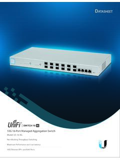
2 The traditional data Center uses a three-tier architecture, with servers segmented into pods based on location, as shown in Figure 1. Figure 1. Traditional three-tier data Center Design The architecture consists of core routers, aggregation routers (sometimes called distribution routers), and access switches. Between the aggregation routers and access switches, Spanning Tree Protocol is used to build a loop-free topology for the Layer 2 part of network. Spanning Tree Protocol provides several benefits: it is simple, and it is a plug-and-play technology requiring little configuration. VLANs are extended within each pod that servers can move freely within the pod without the need to change IP address and default gateway configurations. However, Spanning Tree Protocol cannot use parallel forwarding paths, and it always blocks redundant paths in a VLAN.
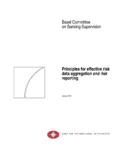
3 In 2010, Cisco introduced virtual-port-channel (vPC) technology to overcome the limitations of Spanning Tree Protocol. vPC eliminates the spanning-tree blocked ports, provides active-active uplink from the access switches to the aggregation routers, and makes full use of the available bandwidth, as shown in Figure 2. With vPC technology, Spanning Tree Protocol is still used as a fail-safe mechanism. vPC technology works well in a relatively small data Center environment in which most traffic consists of northbound and southbound communication between clients and servers. 2020 Cisco and/or its affiliates. All rights reserved. Page 4 of 32 Figure 2. Data Center Design using vPC Since 2003, with the introduction of virtual technology, the computing, networking, and storage resources that were segregated in pods in Layer 2 in the three-tier data Center Design can be pooled.
4 This revolutionary technology created a need for a larger Layer 2 domain, from the access layer to the core layer, as shown in Figure 3. Figure 3. Data Center Design with extended Layer 3 domain With Layer 2 segments extended across all the pods, the data Center administrator can create a central, more flexible resource pool that can be reallocated based on needs. Servers are virtualized into sets of virtual machines that can move freely from server to server without the need to change their operating parameters. 2020 Cisco and/or its affiliates. All rights reserved. Page 5 of 32 With virtualized servers, applications are increasingly deployed in a distributed fashion, which leads to increased east-west traffic. This traffic needs to be handled efficiently, with low and predictable latency. However, vPC can provide only two active parallel uplinks, and so bandwidth becomes a bottleneck in a three-tier data Center architecture.
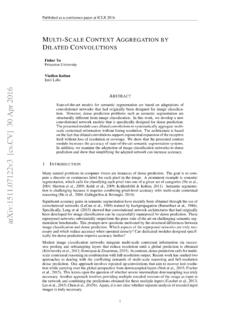
5 Another challenge in a three-tier architecture is that server-to-server latency varies depending on the traffic path used. A new data Center Design called the Clos network based Spine-and-Leaf architecture was developed to overcome these limitations. This architecture has been proven to deliver the high-bandwidth, low-latency, nonblocking server-to-server connectivity. Spine-and-Leaf architecture Figure 4 shows a typical two-tiered Spine-and-Leaf topology. Figure 4. Typical Spine-and-Leaf topology In this two-tier Clos architecture, every lower-tier switch (leaf layer) is connected to each of the top-tier switches (spine layer) in a full-mesh topology. The leaf layer consists of access switches that connect to devices such as servers. The spine layer is the backbone of the network and is responsible for interconnecting all leaf switches. Every leaf switch connects to every spine switch in the fabric.
6 The path is randomly chosen so that the traffic load is evenly distributed among the top-tier switches. If one of the top tier switches were to fail, it would only slightly degrade performance throughout the data Center . If oversubscription of a link occurs (that is, if more traffic is generated than can be aggregated on the active link at one time), the process for expanding capacity is straightforward. An additional spine switch can be added, and uplinks can be extended to every leaf switch, resulting in the addition of interlayer bandwidth and reduction of the oversubscription. If device port capacity becomes a concern, a new leaf switch can be added by connecting it to every spine switch and adding the network configuration to the switch. The ease of expansion optimizes the IT department s process of scaling the network. If no oversubscription occurs between the lower-tier switches and their uplinks, then a nonblocking architecture can be achieved.
7 2020 Cisco and/or its affiliates. All rights reserved. Page 6 of 32 With a Spine-and-Leaf architecture, no matter which leaf switch to which a server is connected, its traffic always has to cross the same number of devices to get to another server (unless the other server is located on the same leaf). This approach keeps latency at a predictable level because a payload only has to hop to a spine switch and another leaf switch to reach its destination. Overlay network Modern virtualized data Center fabrics must meet certain requirements to accelerate application deployment and support DevOps needs. For example, fabrics need to support scaling of forwarding tables, scaling of network segments, Layer 2 segment extension, virtual device mobility, forwarding path optimization, and virtualized networks for multitenant support on shared physical infrastructure.
8 Although the concept of a network overlay is not new, interest in network overlays has increased in the past few years because of their potential to address some of these requirements. Interest in overlay networks has also increased with the introduction of new encapsulation frame formats specifically built for the data Center . These formats include Virtual Extensible LAN (VXLAN), Network Virtualization Using Generic Routing Encapsulation (NVGRE), Transparent Interconnection of Lots of Links (TRILL), and Location/Identifier Separation Protocol (LISP). Network overlays are virtual networks of interconnected nodes that share an underlying physical network, allowing deployment of applications that require specific network topologies without the need to modify the underlying network (Figure 5). Figure 5. Network overlay concept 2020 Cisco and/or its affiliates.
9 All rights reserved. Page 7 of 32 Benefits of a network virtualization overlay include the following: Optimized device functions: Overlay networks allow the separation (and specialization) of device functions based on where a device is being used in the network. An edge or leaf device can optimize its functions and all its relevant protocols based on end-state information and scale, and a core or spine device can optimize its functions and protocols based on link -state updates, optimizing with fast convergence. Fabric scalability and flexibility: Overlay technologies allow the network to scale by focusing scaling on the network overlay edge devices. With overlays used at the fabric edge, the spine and core devices are freed from the need to add end-host information to their forwarding tables. Overlapping addressing: Most overlay technologies used in the data Center allow virtual network IDs to uniquely scope and identify individual private networks.
10 This scoping allows potential overlap in MAC and IP addresses between tenants. The overlay encapsulation also allows the underlying infrastructure address space to be administered separately from the tenant address space. This document reviews several Spine-and-Leaf architecture designs that Cisco has offered in the recent past as well as current designs and those the Cisco expects to offer in the near future to address fabric requirements in the modern virtualized data Center : Cisco FabricPath Spine-and-Leaf network Cisco VXLAN flood-and-learn Spine-and-Leaf network Cisco VXLAN Multiprotocol Border Gateway Protocol (MP-BGP) Ethernet Virtual Private Network (EVPN) Spine-and-Leaf network Cisco Massively Scalable Data Center (MSDC) Layer 3 Spine-and-Leaf network Each section outlines the most important technology components (encapsulation; end-host detection and distribution; broadcast, unknown unicast, and multicast traffic forwarding; underlay and overlay control plane, multitenancy support, etc.)