Transcription of Clarion: A Simple 2A3 Design Project - hagtech.com
1 clarion : A Simple 2A3 Design Project This noted designer offers a novel solution for high line voltages. By Jim Hagerman One of the things that lure DIYers to build SET (single-ended triode) amplifiers is their great sound, due in part to a fabulous first watt of undistorted power. They are also relatively easy to build, having a low level of complexity. This Project offers a one-stop shopping solution for building your own stereo 2A3 amplifier. Why one-stop? Because DIY should be fun. You should not have to search all over the place for rare parts or purchase from multiple sources. That was my motivation behind this Project , to Design and build the best possible 2A3 stereo amplifier using only one parts supplier. Sure, this was a limitation, but it also turned out to be an inspiration for creativity. I chose AES (Antique Electronic Supply), merely because I happen to like their catalog.
2 The Voltage Problem Perusing for parts I noticed that many of the power transformers, especially the filament types, are rated for 115V. Since the voltage across the USA primarily hovers around 120V, this is a problem. Too much input voltage leads to core saturation, overheating, and excessive output voltage. In order to tame this, I came up with the idea of reducing voltage by inserting a small light bulb (the type used for old-style front panel controls) in series with the ac line. In fact, AES has quite a large assortment in various flavors (voltage and current). Perfect! Not only do the bulbs provide the desired voltage drop, but also end up performing a secondary function by acting a fuse. Two birds with one stone, and the cost is low, too. Additionally, the resistive nature of the lamp can be used in conjunction with a capacitor to form a low pass filter on the ac line, thus removing some of the high frequency grunge before it even enters the transformer.
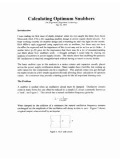
3 Circuit and Operation The circuit shown in Figure 1 shows the complete power supply and one channel of amplification. High voltage for the tubes uses a full-wave tube rectifier into a choke filter operating in continuous conduction mode. This is highly desirable as it eliminates the nasty ac current spikes found in your typical diode-capacitor input topology. Supply filters consist of LCLC sections, each tuned with a series resistance for optimal transient response and damping. Thus, any line or load perturbations do not induce ringing or instability into the output. Left and right channels have split feeds to help reduce crosstalk and further reduce hum. The filament supply for the input/driver tube is from a tap from the same power transformer. The center tap is used to balance the supply around 0V and small series resistors drop the voltage to nominal (winding designed for higher current operation).
4 I added a small film capacitor to form an RC low pass filter, which again helps to eliminate differential RF hash and other non-60Hz noise components. Two separate filament transformers are used to heat the output tube cathodes. These have center taps on the secondary, which allow for a balanced cathode drive and no need for hum pots. You will note the lamps on their primaries to help drop the line voltage. Unfortunately, during testing I discovered that the cold filaments draw two to three times the normal operating current, routinely blowing up lamps. Therefore, I changed the lamp to one with a higher rating (#47) and that solved the problem. The voltage drop isn t as high as I wanted, but the solution was reliable. During power-up the lamps glow brightly for about two seconds before they settle down to a dim glow. Figure 1. Schematic.
5 The amplifier section is very straightforward with a single stage input/driver. This results in a relatively low sensitivity amplifier, requiring about 4 Vrms input driving the output to clipping. Normally, designers add an extra gain stage, but I felt this was a reasonable compromise for the sake of simplicity. Most active linestages will be able to drive this without issue. You could also add a large capacitor to bypass R13, thereby increasing gain. The input tube is a dual triode with sections shared between channels. I chose the robust 5687 (closest modern equivalent is the ECC99) for this purpose, as it has low output impedance and superb sonics. You can also use a Russian 6H30, although it has a different pinout. The output stage is run in self-bias mode at -40V grid, 55mA plate current, and 225V plate-cathode.
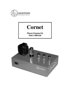
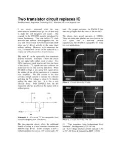
6 This operating point has less power dissipation compared to most 2A3 designs, and I think sounds better while offering improved tube life. Coupling between stages is RC, and I use a low 33k value for bias, as this tends to reduce the effects of grid current modulation. In the cathode tail I insert a #49 (2V) lamp to act as an indicator of tube current. Both this and the 680 ohm bias resistor are bypassed by a large 10uF film capacitor and 100uF electrolytic. Additionally, another 10uF film capacitor connects to the B+ supply, providing a bit of parafeed localized output loop decoupling. Construction The hardest part of building this amplifier (for me) is cutting and drilling the chassis. After deciding on a logical placement of components, I drew up a mechanical Design (Figure 3). Using this guide, I drilled all of the small holes with a step-drill.
7 Larger holes came out with hole-punches, and the rectangular cutouts were done using elbow grease and a file. After a bath in the sink to remove oils and fingerprints, the result was more than acceptable. Normally, at this point I spray paint with a hammertone or other suitable finish, but this time spent the money to get it professionally powder coated. It s a thick, glossy, and durable finish that doesn t chip, crack, or peel off. I had the transformer bells done in blue and the main chassis in white. Figure 2. Machined chassis prior to painting. Figure 3. Mechanical drawing of chassis. Next up is mounting components. I like to use stainless steel hardware for everything, as it is reasonably non-magnetic and doesn t have rust problems. All transformers, chokes, and sockets are mounted using rubber washers to provide a bit of vibration damping and decoupling from the chassis.
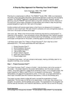
8 The large electrolytic capacitors are then glued to the underside of the chassis with silicone. Figure 4. Chassis innards. Wiring is point to point. Yes, I very much prefer circuit boards, but this circuit is so Simple that given a decent component placement, the wiring was not at all tedious. I took my time and spread it out over several days, allowing me to glue down parts between sessions. I don t like to leave heavy components floating in space such that they can vibrate. It also helps to keep capacitors spaced far enough from power resistors to reduce thermal coupling. I added terminal strips on the socket mounting screws to facilitate organized wiring. Unfortunately, there was no easy way to route line voltage to the filament transformers, which must be mounted next to the output tubes.
9 Careless wiring can lead to hum and/or instability. I tie-wrapped the ac wires down against the aluminum chassis. Input wires are coaxial, necessary to shielding. Apparently the attention to details worked, as this amplifier is unbelievably hum-free and quiet. Figure 5. Completed amplifier. Testing Firing up an amplifier for the first time can be a scary proposition. Always double-check your work first. Then put on some safety glasses. Power it up without any tubes plugged in. This way you can check the various secondary voltages. Try it again with the output tubes installed. Check the #47 lamps and filament voltages. Now add the rectifier tube. Again, check operating voltages, especially all of the ac and dc points in the supply. The output tube should achieve it s operating bias and the #49 lamps will light up. Finally, add the driver tube.
10 If all is well, try loading the output terminals with power 8-ohm resistor loads and apply an input signal. Of course, an oscilloscope comes in real handy at this point. The prototype measured a power bandwidth of 12Hz to 65kHz. That s pretty fast for an SET! Step response wasn t quite perfect, due to a slight ultrasonic ringing in the output transformer, but otherwise textbook. It was not instability, as no feedback is used in this Design . Power output at the onset of clipping (which is very soft) was Distortion at 1W was , nearly all 2nd harmonic. SNR was a superb 86dBA below 1W. This amplifier is so quiet that even using a 105dB horn loudspeaker you had to get within inches to hear the noise floor. Sonics Finally, the part we were all waiting for. I did most of my listening tests using Horn Shoppe Horns , which have no crossover and are about 94dB efficient.