Transcription of Ω) CLASS-T™ DIGITAL AUDIO AMPLIFIER DRIVER USING …
1 Tripath Technology, Inc. - Technical Information 1 TA2020 TA2020-020 STEREO 20W (4 ) CLASS-T DIGITAL AUDIO AMPLIFIER DRIVER USING DIGITAL POWER PROCESSING (DPP ) TECHNOLOGY Technical Information Revision March 2005 GENERAL DESCRIPTION The TA2020-020 is a 20W (4 ) continuous average per channel Class-T DIGITAL AUDIO Power AMPLIFIER IC USING Tripath s proprietary DIGITAL Power Processing (DPPTM) technology. Class-T amplifiers offer both the AUDIO fidelity of Class-AB and the power efficiency of Class-D amplifiers. APPLICATIONS DVD Players Mini/Micro Component Systems Computer / PC Multimedia Cable Set-Top Products Televisions Battery Powered Systems BENEFITS Fully integrated solution with internal FETs Easier to design-in than Class-D Reduced system cost with minimal heat sink requirement Dramatically improves efficiency versus Class-AB amplifiers Signal fidelity equal to high quality linear amplifiers High dynamic range compatible with DIGITAL media such as CD and DVD, and internet AUDIO FEATURES Class-T architecture Single Supply Operation Audiophile Quality Sound THD+N @ 10W 4 THD+N @12W 4 IHF-IM @ 1W 4 High Power 25W @ 4 , 10% THD+N, VDD= 22W @ 4 , 10% THD+N, VDD= 13W @ 8 , 10% THD+N.
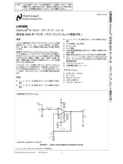
2 VDD= High Efficiency 88% @ 12W 8 81% @ 20W 4 Dynamic Range = 99dB Mute and Sleep inputs Turn-on & turn-off pop suppression Over-current protection Over-temperature protection Bridged outputs 32-pin SSIP package TYPICAL PERFORMANCE THD+N (%)Output Power (W)THD+N versus Output PowerVDD = = 12V/Vf = 1kHzBW = 22Hz - 22kHz1234567891020500mRL= 8 RL= 4 Tripath Technology, Inc. - Technical Information 2 TA2020 ABSOLUTE MAXIMUM RATINGS (Note 1) SYMBOL PARAMETER Value UNITS VDD Supply Voltage 16 V V5 Input Section Supply Voltage V SLEEP SLEEP Input Voltage to V MUTE MUTE Input Voltage to V5+ V ESDHBM ESD Susceptibility, All pins except 2, 30 Human Body Model (Note2) Pins 2, 30 2000 1000 V V ESDMM ESD Susceptibility, Machine Model (Note 3) 200 V TSTORE Storage Temperature Range -40 to 150 C TA Operating Free-air Temperature Range -40 to 85 C TJ Junction Temperature 150 C Note 1.
3 Absolute Maximum Ratings indicate limits beyond which damage to the device may occur. See the table below for Operating Conditions. Note 2: Human body model, 100pF discharged through a resistor. Note 3: Machine model, 220pF discharged through all pins. OPERATING CONDITIONS (Note 4) SYMBOL PARAMETER MIN. TYP. MAX. UNITS VDD Supply Voltage V VIH High-level Input Voltage (MUTE, SLEEP) V VIL Low-level Input Voltage (MUTE, SLEEP) 1 V Note 4: Recommended Operating Conditions indicate conditions for which the device is functional. See Electrical Characteristics for guaranteed specific performance limits.
4 THERMAL CHARACTERISTICS SYMBOL PARAMETER VALUE UNITS JC Junction-to-case Thermal Resistance C/W JA Junction-to-ambient Thermal Resistance 15 C/W Tripath Technology, Inc. - Technical Information 3 TA2020 ELECTRICAL CHARACTERISTICS (Notes 6, 7) See Test/Application Circuit. Unless otherwise specified, VDD = , f = 1kHz, Measurement Bandwidth = 22kHz, RL = 4 , TA = 25 C. SYMBOL PARAMETER CONDITIONS MIN. TYP. MAX. UNITSPO Output Power (Continuous Average/Channel) THD+N = RL = 4 RL = 8 THD+N = 10% RL = 4 RL = 8 11 7 18 10 W W W W PO Output Power (VDD= ) (Continuous Average/Channel)
5 THD+N = RL = 4 RL = 8 THD+N = 10% RL = 4 RL = 8 25 W W W W IDD,MUTE Mute Supply Current MUTE = VIH 7 mA IDD, SLEEP Sleep Supply Current SLEEP = VIH 2 mA Iq Quiescent Current VIN = 0 V 64 75 mA THD + N Total Harmonic Distortion Plus Noise PO = 10W/Channel % IHF-IM IHF Intermodulation Distortion 19kHz, 20kHz, 1:1 (IHF) % SNR Signal-to-Noise Ratio A-Weighted, POUT = 20W, RL = 4 99 dB CS Channel Separation 0dBr = 1W, RL = 4 , f = 1 kHz 70 80 dB PSRR Power Supply Rejection Ratio VDD = 9V to Vripple = 100mV, f=1kHz 65 75 65 dB dB Power Efficiency POUT = 12W/Channel, RL = 8 88 % VOFFSET Output Offset Voltage No Load, MUTE = Logic low 50 150 mV VOH High-level output voltage (FAULT & OVERLOADB)
6 V VOL Low-level output voltage (FAULT & OVERLOADB) 1 V eOUT Output Noise Voltage A-Weighted, input AC grounded 100 V Note 6: Minimum and maximum limits are guaranteed but may not be 100% tested.
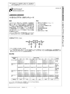
7 Note 7: For operation in ambient temperatures greater than 25 C, the device must be derated based on the maximum junction temperature and the thermal resistance determined by the mounting technique. Tripath Technology, Inc. - Technical Information 4 TA2020 PIN DESCRIPTION TA2020 PINOUT Pin Function Description 2, 8 V5D, V5A DIGITAL 5 VDC, Analog 5 VDC 3, 7, 16 AGND1, AGND2, AGND3 Analog Ground 4 REF Internal reference voltage; approximately 6 OVERLOADB A logic low output indicates the input signal has overloaded the AMPLIFIER . 9, 12 OAOUT1, OAOUT2 Input stage output pins 10, 13 INV1, INV2 Single-ended inputs. Inputs are a virtual ground of an inverting opamp with approximately bias. 11 MUTE When set to logic high, both amplifiers are muted and in idle mode. When low (grounded), both amplifiers are fully operational.
8 If left floating, the device stays in the mute mode. Ground if not used. 14 BIASCAP Input stage bias voltage (approximately ). 17 SLEEP When set to logic high, device goes into low power mode. If not used this pin should be grounded. Can be pulled-up to VDD with a 1M resistor (100K minimum). 18 FAULT A logic high output indicates thermal overload, or an output is shorted to ground, or another output. 19, 28 PGND2, PGND1 Power Ground (high current) 20 DGND DIGITAL Ground. Should be connected to AGND locally at TA2020-020. 21, 23, 26, 24 OUTP2 OUTP1 & OUTM1 Bridged output pairs 22, 25 VDD2, VDD1 Supply pin for high current H-bridges, nominally 1, 5, 15 NC Not connected 27 VDDA Analog 29 CPUMP Charge pump output (nominally 10V above VDDA) 30 5 VGEN Regulated 5 VDC source used to supply power to the input section (pins 2 & 8).
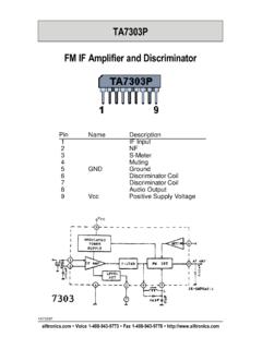
9 31, 32 DCAP2, DCAP1 Charge pump switching pins. DCAP1 (pin 32) is a free running 300kHz square wave between VDDA and DGND ( nominal). DCAP2 (pin 31) is level shifted 10 volts above DCAP1 (pin 32) with the same amplitude ( nominal), frequency, and phase as DCAP1. 5 VGENNCFAULTPGND2 DGNDOUTP2 VDD2 OUTM2 OUTM1 VDD1 OUTP1 NCVDDAPGND1 CPUMPDCAP2 AGND3 BIASCAPINV2 OAOUT2 MUTEINV1 OAOUT1V5 AAGND2 OVERLOADBREFAGND1V5 DDCAP13016171819202122232425262728291151 4131110129876543232-pin SSIP Package(Front View)3231 SLEEPNC Tripath Technology, Inc. - Technical Information 5 TA2020 APPLICATION / TEST CIRCUIT TA2020-020RL4 or *8 MUTEFAULTOVERLOADB(+ ) 17RZ10 ,1 ++5 VSLEEP5V5V+ , 1%45NC1M * Use Co = F and Cz= for 8 Ohm loadsVDD1 PGND1 VDD1 PGND1 VDD2 VDD2 PGND2 PGND2 Note: Analog and DIGITAL /Power Grounds must be connected locally at the Pin , 16 VVDD2 VDD+++Processing&ModulationProcessing&Mo dulation* , 3A8(Pin 7)Analog GroundDigital/Power Ground(Pin 28)(Pin 28)(Pin 19)(Pin 19)To Pin 2,8RI20K (Pin 3)RF20K RI20K 1 NCNCAGND316180uF, 16 VCSWCSW* , 3 ARL4 or *8 Lo10uH, 3 ALo10uH, 3A* * ,1/2W(Pin 28)(Pin 19)AGND1 VDD2 (pin 22)VDD1 (pin 25)DHDHDHDHVDD1 (pin 25)VDD2 (pin 22)Diodes (DO and DH) are Motorola MBRS130T3 (the DH diodes are required for VDD> ) Tripath Technology, Inc.
10 - Technical Information 6 TA2020 EXTERNAL COMPONENTS DESCRIPTION (Refer to the Application/Test Circuit) Components Description RI Inverting input resistance to provide AC gain in conjunction with RF. This input is biased at the BIASCAP voltage (approximately ). RF Feedback resistor to set AC gain in conjunction with RI)R/R(12 AIFV=. Please refer to the AMPLIFIER Gain paragraph, in the Application Information section. CI AC input coupling capacitor which, in conjunction with RI, forms a highpass filter at )CR2(1fIIC =. RREF Bias resistor. Locate close to pin 4 and ground at pin 7. CA BIASCAP decoupling capacitor. Should be located close to pin 14 and grounded at pin 7. CD Charge pump input capacitor. This capacitor should be connected directly between pins 31 and 32 and located physically close to the TA2020-020.