Transcription of Click DS18B20 Prorammale Resoltion 1-Wire Diital …
1 General DescriptionThe DS18B20 digital thermometer provides 9-bit to 12-bit Celsius temperature measurements and has an alarm function with nonvolatile user-programmable upper and lower trigger points. The DS18B20 communicates over a 1-Wire bus that by definition requires only one data line (and ground) for communication with a central micro-processor. In addition, the DS18B20 can derive power directly from the data line ( parasite power ), eliminating the need for an external power supply. Each DS18B20 has a unique 64-bit serial code, which allows multiple DS18B20s to function on the same 1-Wire bus. Thus, it is simple to use one microprocessor to control many DS18B20s distributed over a large area.
2 Applications that can benefit from this feature include HVAC environmental controls, temperature monitoring systems inside buildings, equipment, or machinery, and process monitoring and control Thermostatic Controls Industrial Systems Consumer Products Thermometers Thermally Sensitive SystemsBenefits and Features Unique 1-Wire Interface Requires Only One Port Pin for Communication Reduce Component Count with Integrated Temperature Sensor and EEPROM Measures temperatures from -55 C to +125 C (-67 F to +257 F) C Accuracy from -10 C to +85 C Programmable Resolution from 9 Bits to 12 Bits No External Components Required Parasitic Power Mode Requires Only 2 Pins for Operation (DQ and GND) Simplifies Distributed Temperature-Sensing Applications with Multidrop Capability Each Device Has a Unique 64-Bit Serial Code Stored in On-Board ROM Flexible User-Definable Nonvolatile (NV) Alarm Settings with Alarm Search Command Identifies Devices with temperatures Outside Programmed Limits Available in 8-Pin SO (150 mils), 8-Pin SOP, and 3-Pin TO-92 Packages19-7487; Rev 4.
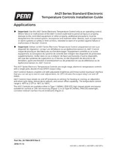
3 1/15 Ordering Information appears at end of data is a registered trademark of Maxim Integrated Products, (150 mils)(DS18B20Z) +14378561234+ SOP(DS18B20U)DS18B20123 GNDDQVDD1 123 TOP VIEWTO-92 ( DS18B20 ) DS18B20 Programmable Resolution 1-Wire Digital Thermometer Pin ConfigurationsVoltage Range on Any Pin Relative to Ground .. to + Temperature Range ..-55 C to +125 CStorage Temperature Range ..-55 C to +125 CSolder Temperature ..Refer to the IPC/JEDEC J-STD-020 Specification.(-55 C to +125 C; VDD = to )Note 1: All voltages are referenced to ground. Note 2: The Pullup Supply Voltage specification assumes that the pullup device is ideal, and therefore the high level of the pullup is equal to VPU.
4 In order to meet the VIH spec of the DS18B20 , the actual supply rail for the strong pullup transis-tor must include margin for the voltage drop across the transistor when it is turned on; thus: VPU_ACTUAL = VPU_IDEAL + VTRANSISTOR. Note 3: See typical performance curve in Figure 4: Logic-low voltages are specified at a sink current of 5: To guarantee a presence pulse under low voltage parasite power conditions, VILMAX may have to be reduced to as low as Note 6: Logic-high voltages are specified at a source current of 7: Standby current specified up to +70 C. Standby current typically is 3 A at +125 8: To minimize IDDS, DQ should be within the following ranges: GND DQ GND + or VDD DQ 9: Active current refers to supply current during active temperature conversions or EEPROM 10: DQ line is high ( high-Z state).
5 Note 11: Drift data is based on a 1000-hour stress test at +125 C with VDD = VoltageVDDL ocal power (Note 1)+ + Supply VoltageVPUP arasite power (Notes 1, 2)+ + power + ErrortERR-10 C to +85 C (Note 3) C-55 C to +125 C 2 Input Logic-LowVIL(Notes 1, 4, 5) + Logic-HighVIHL ocal power(Notes 1,6)+ lower of orVDD + power + CurrentILVI/O = CurrentIDDS(Notes 7, 8)7501000nAActive CurrentIDDVDD = 5V (Note 9) Input CurrentIDQ(Note 10)5 ADrift(Note 11) CDS18B20 Programmable Resolution 1-Wire Digital Thermometer Integrated 2 Absolute Maximum RatingsThese are stress ratings only and functional operation of the device at these or any other conditions above those indicated in the operation sections of this specification is not implied.
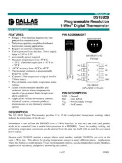
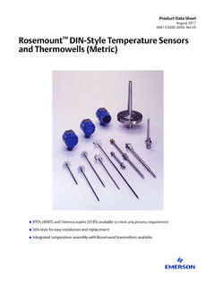
6 Exposure to absolute maximum rating conditions for extended periods of time may affect Electrical Characteristics(-55 C to +125 C; VDD = to )(-55 C to +125 C; VDD = to )Note 12: See the timing diagrams in Figure 2. Note 13: Under parasite power, if tRSTL > 960 s, a power-on reset can 1. Typical Performance CurvePARAMETERSYMBOLCONDITIONSMINTYPMAXU NITSNV Write Cycle TimetWR210msEEPROM WritesNEEWR-55 C to +55 C50kwritesEEPROM Data RetentiontEEDR-55 C to +55 C10yearsPARAMETERSYMBOLCONDITIONSMINTYPM AXUNITST emperature Conversion TimetCONV9-bit resolution(Note 12) resolution37512-bit resolution750 Time to Strong Pullup OntSPONS tart convert T command issued10 sTime SlottSLOT(Note 12)60120 sRecovery TimetREC(Note 12)1 sWrite 0 Low TimetLOW0(Note 12)60120 sWrite 1 Low TimetLOW1(Note 12)115 sRead Data ValidtRDV(Note 12)15 sReset Time HightRSTH(Note 12)480 sReset Time LowtRSTL(Notes 12, 13)480 sPresence-Detect HightPDHIGH(Note 12)1560 sPresence-Detect LowtPDLOW(Note 12)
7 60240 sCapacitanceCIN/OUT25pFDS18B20 TYPICAL ERROR ERROR ( C)070102030405060 TEMPERATURE ( C)+3s ERRORMEAN ERROR-3s ERRORDS18B20 Programmable Resolution 1-Wire Digital Thermometer Integrated 3AC Electrical Characteristics NV MemoryAC Electrical CharacteristicsFigure 2. Timing DiagramsPINNAMEFUNCTIONSO SOPTO-921, 2, 6, 7, 82, 3, 5, 6, 7 Connection383 VDDO ptional VDD. VDD must be grounded for operation in parasite power Input/Output. Open-drain 1-Wire interface pin. Also provides power to the device when used in parasite power mode (see the Powering the DS18B20 section.) 541 GNDG roundSTART OF NEXT CYCLE1-WIRE WRITE ZERO TIME SLOTtRECtSLOTtLOW01-WIRE READ ZERO TIME SLOTtRECtSLOTSTART OF NEXT CYCLEtRDV1-WIRE RESET PULSE1-WIRE PRESENCE DETECTtRSTLtRSTHtPDIHPRESENCE DETECTtPDLOWRESET PULSE FROM HOSTDS18B20 Programmable Resolution 1-Wire Digital Thermometer Integrated 4 Pin DescriptionOverviewFigure 3 shows a block diagram of the DS18B20 , and pin descriptions are given in the Pin Description table.
8 The 64-bit ROM stores the device s unique serial code. The scratchpad memory contains the 2-byte temperature register that stores the digital output from the temperature sensor. In addition, the scratchpad provides access to the 1-byte upper and lower alarm trigger registers (TH and TL) and the 1-byte configuration register. The configura-tion register allows the user to set the resolution of the temperature-to-digital conversion to 9, 10, 11, or 12 bits. The TH, TL, and configuration registers are nonvolatile (EEPROM), so they will retain data when the device is powered DS18B20 uses Maxim s exclusive 1-Wire bus proto-col that implements bus communication using one control signal.
9 The control line requires a weak pullup resistor since all devices are linked to the bus via a 3-state or open-drain port (the DQ pin in the case of the DS18B20 ). In this bus system, the microprocessor (the master device) identifies and addresses devices on the bus using each device s unique 64-bit code. Because each device has a unique code, the number of devices that can be addressed on one bus is virtually unlimited. The 1-Wire bus protocol, including detailed explanations of the commands and time slots, is covered in the 1-Wire Bus System feature of the DS18B20 is the ability to oper-ate without an external power supply.
10 Power is instead supplied through the 1-Wire pullup resistor through the DQ pin when the bus is high. The high bus signal also charges an internal capacitor (CPP), which then supplies power to the device when the bus is low. This method of deriving power from the 1-Wire bus is referred to as para-site power. As an alternative, the DS18B20 may also be powered by an external supply on Measuring TemperatureThe core functionality of the DS18B20 is its direct-to-digital temperature sensor. The resolution of the tempera-ture sensor is user-configurable to 9, 10, 11, or 12 bits, corresponding to increments of C, C, C, and C, respectively.