Transcription of 'CMOS Power Consumption and CPD Calculation'
1 1 CMOS Power Consumptionand Cpd CalculationSCAA035 BJune 1997 2 IMPORTANT NOTICET exas Instruments (TI) reserves the right to make changes to its products or to discontinue anysemiconductor product or service without notice, and advises its customers to obtain the latestversion of relevant information to verify, before placing orders, that the information being reliedon is warrants performance of its semiconductor products and related software to the specificationsapplicable at the time of sale in accordance with TI s standard warranty. Testing and other qualitycontrol techniques are utilized to the extent TI deems necessary to support this testing of all parameters of each device is not necessarily performed, except thosemandated by government applications using semiconductor products may involve potential risks of death,personal injury, or severe property or environmental damage ( Critical Applications ).
2 TI SEMICONDUCTOR PRODUCTS ARE NOT DESIGNED, INTENDED, AUTHORIZED, ORWARRANTED TO BE SUITABLE FOR USE IN LIFE-SUPPORT APPLICATIONS, DEVICESOR SYSTEMS OR OTHER CRITICAL of TI products in such applications is understood to be fully at the risk of the of TI products in such applications requires the written approval of an appropriate TI concerning potential risk applications should be directed to TI through a local SCsales order to minimize risks associated with the customer s applications, adequate design andoperating safeguards should be provided by the customer to minimize inherent orprocedural assumes no liability for applications assistance, customer product design, softwareperformance, or infringement of patents or services described herein. Nor does TI warrant orrepresent that any license, either express or implied, is granted under any patent right, copyright,mask work right, or other intellectual property right of TI covering or relating to any combination,machine, or process in which such semiconductor products or services might be or are 1997, Texas Instruments IncorporatediiiContentsTitlePageIntroduc tion1.
3 Power - Consumption Components1.. Static Power Consumption1.. Dynamic Power Consumption3.. Transient Power Consumption3.. Capacitive-Load Power Consumption4.. Power -Dissipation Capacitance (Cpd) in CMOS Circuits5.. Testing Considerations5.. Test Conditions6.. Calculating Cpd6.. Cpd Measurement Procedures6.. Determination of Cpd (Laboratory Testing)7.. Comparison of Supply Current Versus Frequency9.. Power Economy12.. Conclusion12.. Acknowledgment12.. List of IllustrationsFigureTitlePage1 CMOS Inverter Mode for Static Power Consumption2.. 2 Model Describing Parasitic Diodes Present in CMOS Inverter2.. 3 Hex Inverter AHC046.. 4 Several Circuits Switching, AHC3747.. 5 ICC vs Frequency for AHC007.. 6 Input Waveform8.. 7 Power Consumption With All Outputs Switching10.. 8 Power Consumption With a Single Output Switching11.. iv1 IntroductionReduction of Power Consumption makes a device more reliable. The need for devices that consume a minimum amount of powerwas a major driving force behind the development of CMOS technologies.
4 As a result, CMOS devices are best known for lowpower Consumption . However, for minimizing the Power requirements of a board or a system, simply knowing that CMOS devices may use less Power than equivalent devices from other technologies does not help much. It is important to know not onlyhow to calculate Power Consumption , but also to understand how factors such as input voltage level, input rise time, Power -dissipation capacitance, and output loading affect the Power Consumption of a device. This application report addressesthe different types of Power Consumption in a CMOS logic circuit, focusing on calculation of Power -dissipation capacitance(Cpd), and, finally, the determination of total Power Consumption in a CMOS main topics discussed are: Power - Consumption components Static Power Consumption Dynamic Power Consumption Power -dissipation capacitance (Cpd) in CMOS circuits Cpd comparison among different families Power economy ConclusionPower- Consumption ComponentsHigh frequencies impose a strict limit on Power Consumption in computer systems as a whole.
5 Therefore, Power consumptionof each device on the board should be minimized. Power calculations determine Power -supply sizing, current requirements,cooling/heatsink requirements, and criteria for device selection. Power calculations also can determine the maximum reliableoperating components determine the Power Consumption in a CMOS circuit: Static Power Consumption Dynamic Power consumptionCMOS devices have very low static Power Consumption , which is the result of leakage current. This Power Consumption occurswhen all inputs are held at some valid logic level and the circuit is not in charging states. But, when switching at a high frequency,dynamic Power Consumption can contribute significantly to overall Power Consumption . Charging and discharging a capacitiveoutput load further increases this dynamic Power application report addresses Power Consumption in CMOS logic families (5 V and V) and describes the methods forevaluating both static and dynamic Power Consumption .
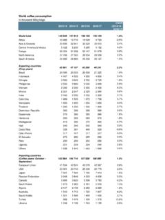
6 Additional information is also presented to help explain the causes ofpower Consumption , and present possible solutions to minimize Power Consumption in a CMOS Power ConsumptionTypically, all low-voltage devices have a CMOS inverter in the input and output stage. Therefore, for a clear understanding ofstatic Power Consumption , refer to the CMOS inverter modes shown in Figure 1. 2 Logic Level = 0 Logic Level = 1 Case 1 VCCP-DeviceN-DeviceGNDL ogic Level = 1 Logic Level = 0 Case 2 VCCP-DeviceN-DeviceGNDF igure 1. CMOS Inverter Mode for Static Power ConsumptionAs shown in Figure 1, if the input is at logic 0, the n-MOS device is OFF, and the p-MOS device is ON (Case 1). The output voltageis VCC, or logic 1. Similarly, when the input is at logic 1, the associated n-MOS device is biased ON and the p-MOS device isOFF. The output voltage is GND, or logic 0. Note that one of the transistors is always OFF when the gate is in either of these logicstates.
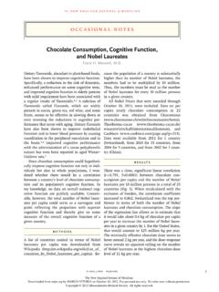
7 Since no current flows into the gate terminal, and there is no dc current path from VCC to GND, the resultant quiescent(steady-state) current is zero, hence, static Power Consumption (Pq) is , there is a small amount of static Power Consumption due to reverse-bias leakage between diffused regions and thesubstrate. This leakage inside a device can be explained with a simple model that describes the parasitic diodes of a CMOS inverter, as shown in Figure +N+P+N+N-WellVOVIP+N+ P-SubstrateGNDGNDVIVO(NMOS)(PMOS)VCCVCCF igure 2. Model Describing Parasitic Diodes Present in CMOS Inverter3 The source drain diffusion and N-well diffusion form parasitic diodes. In Figure 2, the parasitic diodes are shown between theN-well and substrate. Because parasitic diodes are reverse biased, only their leakage currents contribute to static powerconsumption. The leakage current (Ilkg)of the diode is described by the following equation:Ilkg+is eqV kT*1 Where:is= reverse saturation currentV = diode voltagek = Boltzmann s constant ( 10 23 J/K)q = electronic charge ( 10 19 C)T = temperatureStatic Power Consumption is the product of the device leakage current and the supply voltage.
8 Total static Power Consumption ,PS, can be obtained as shown in equation +S(leakage current) (supply voltage)Most CMOS data sheets specify an ICC maximum in the 10- A to 40- A range, encompassing total leakage current and othercircuit features that may require some static current not considered in the simple inverter leakage current ICC (current into a device), along with the supply voltage, causes static Power Consumption in the CMOS devices. This static Power Consumption is defined as quiescent, or PS, and can be calculated by equation +VCC ICCW here:VCC= supply voltageICC= current into a device (sum of leakage currents as in equation 2)Another source of static current is ICC. This results when the input levels are not driven all the way to the rail, causing the inputtransistors to not switch off Power ConsumptionThe dynamic Power Consumption of a CMOS IC is calculated by adding the transient Power Consumption (PT), andcapacitive-load Power Consumption (PL).
9 Transient Power ConsumptionTransient Power Consumption is due to the current that flows only when the transistors of the devices are switching from one logicstate to another. This is a result of the current required to charge the internal nodes (switching current) plus the through current(current that flows from VCC to GND when the p-channel transistor and n-channel transistor turn on briefly at the same timeduring the logic transition). The frequency at which the device is switching, plus the rise and fall times of the input signal, as wellas the internal nodes of the device, have a direct effect on the duration of the current spike. For fast input transition rates, thethrough current of the gate is negligible compared to the switching current. For this reason, the dynamic supply current isgoverned by the internal capacitance of the IC and the charge and discharge current of the load capacitance.(1)(2)(3) 4 Transient Power Consumption can be calculated using equation +Cpd V2CC fI NSWW here:PT= transient Power consumptionVCC= supply voltagefI= input signal frequencyNSW= number of bits switchingCpd= dynamic Power -dissipation capacitanceIn the case of single-bit switching, NSW in equation 4 is supply current is dominant in CMOS circuits because most of the Power is consumed in moving charges in the parasiticcapacitor in the CMOS gates.
10 As a result, the simplified model of a CMOS circuit consisting of several gates can be viewed asone large capacitor that is charged and discharged between the Power -supply rails. Therefore, the Power dissipation capacitance(Cpd) is often specified as a measure of this equivalent capacitance and is used to approximate the dynamic Power is defined as the internal equivalent capacitance of a device calculated by measuring operating current without loadcapacitance. Depending on the output switching capability, Cpd can be measured with no output switching (output disabled) orwith any of the outputs switching (output enabled). Cpd is discussed in greater detail in the next Power ConsumptionAdditional Power is consumed in charging external load capacitance and is dependent on switching frequency. The followingequation can be used to calculate this Power if all outputs have the same load and are switching at the same output +CL V2CC fO NSW(CLis the load per output)Where:PL= capacitive-load Power consumptionVCC= supply voltagefO= output signal frequencyCL= external (load) capacitanceNSW= total number of outputs switchingIn the case of different loads and different output frequencies at all outputs, equation 6 is used to calculate capacitive-loadpower +S(CLn fOn) V2 CCWhere: = sum of n different frequencies and loads at n different outputsfOn= all different output frequencies at each output, numbered 1 through n (Hz)VCC= supply voltage (V)CLn= all different load capacitances at each output, numbered 1 through n.