Transcription of Component Instantiation - College of Engineering
1 Component Instantiation Component Instantiation is a concurrent statement that can be used to connect circuit elements at a very low level or most frequently at the top level of a design. A VHDL design description written exclusively with Component instantiations is known as Structural VHDL. Structural VHDL defines behavior by describing how components are connected. The Instantiation statement connects a declared Component to signals in the architecture. The Instantiation has 3 key parts: Label - Identifies unique instance of Component Component Type - Select the desired declared Component Port Map - Connect Component to signals in the architecture u1 : reg1 PORT MAP(d=>d0,clk=>clk,q=>q0);. label the pin clk on reg1. wire that pin clock is connected to Component type When instantiating components: Local and actual must be of same data type. Local and actual must be of compatible modes. Locally declared signals do not have an associated mode and can connect to a local port of any mode.
2 Component Instantiation 1. Labels Labels are used to provide internal documentation. May be used with: Concurrent Assertion Statements Concurrent Signal Assignments Process Statements Loop Statements Generate Statements Must be used with: Component Instantiation Statements Component Instantiation 2. Component Instantiation Example: --5:1 mux, 1 bit wide LIBRARY ieee;. USE ;. LIBRARY adk;. USE ;. ENTITY mux5_1_1wide IS. PORT(. a_input : IN STD_LOGIC; --input a b_input : IN STD_LOGIC; --input b c_input : IN STD_LOGIC; --input c d_input : IN STD_LOGIC; --input d e_input : IN STD_LOGIC; --input e sel : IN STD_LOGIC_VECTOR(2 DOWNTO 0); --sel input z_out : OUT STD_LOGIC --data out );. END mux5_1_1wide;. ARCHITECTURE beh OF mux5_1_1wide IS. SIGNAL temp0, temp1, temp2, temp3 : STD_LOGIC;. Component mux21 PORT( a0,a1,s0 : IN STD_LOGIC;. y : OUT STD_LOGIC); END Component ;. Component inv01 PORT( a : IN STD_LOGIC;. y : OUT STD_LOGIC); END Component .
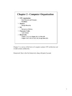
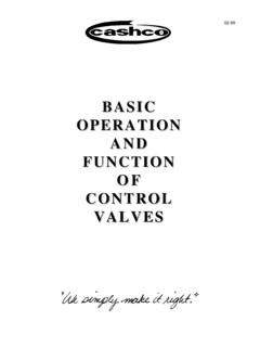
3 BEGIN. U1 : mux21 PORT MAP(a0 => a_input, a1 => b_input, s0 => sel(0), y => temp0);. U2 : mux21 PORT MAP(a0 => c_input, a1 => d_input, s0 => sel(0), y => temp1);. U3 : mux21 PORT MAP(a0 => temp0, a1 => temp1, s0 => sel(1), y => temp2);. U4 : mux21 PORT MAP(a0 => temp2, a1 => e_input, s0 => sel(2), y => temp3);. U5 : inv01 PORT MAP(a => temp3, y => z_out);. END beh;. Component Instantiation 3. The synthesized structural 5:1 mux The synthesized mux is a faithful representation of our structural VHDL. Actually the synthesis tools hands are tied. The structural VHDL told exactly how the components were to be wired. It also specified exactly what logic cells were to be used. The synthesis tool actually had nothing to do except make the edif netlist and schematic. U1. a_input U1. A0. Y. A1 S0. b_input 0. U3. A0. U2 U4. c_input A0. Y. A0 U5. A1 S0. d_input S0. Y. S0. Y A Y z_out sel(2:0) A1 A1 1x 1. 0 2. e_input Component Instantiation 4.
4 Component Instantiation (cont.). A few notes about the structural 5:1 mux code: The logic cells used here were in a library called adk. To access these cells the declaration of this library was necessary at the top of the file. LIBRARY adk;. USE ;. Before we can use the cells in an Instantiation statement, we must declare them. This is seen in the statements: Component mux21 PORT( a0,a1,s0 : IN STD_LOGIC;. y : OUT STD_LOGIC); END Component ;. Component inv01 PORT( a : IN STD_LOGIC;. y : OUT STD_LOGIC); END Component ;. To wire the mux21 cells together, temporary signals, temp0, temp1, temp2 and temp3 were declared. SIGNAL temp0, temp1, temp2, temp3 : STD_LOGIC;. Finally, the Component instantiations stitch the design together. U1 : mux21 PORT MAP(a0 => a_input, a1 => b_input, s0 => sel(0), y => temp0);. The PORT MAP statement describes the connections between pins of the cell and the signals. The connections are described by the format: association operator pin_on_module => signal_name, The first name is the module pin name, the second is the name of the signal the pin is to be connected to.
5 This format is called named association. With named association, the order of associations is not required to be in the same order as port declaration in the Component . Component Instantiation 5. Another example at a higher level of abstraction: LIBRARY ieee;. USE ;. ENTITY arthur IS. PORT(. clk : IN STD_LOGIC; --clock input enbl : IN STD_LOGIC; --enable for arthur adv : IN STD_LOGIC; --advance the state pulse : OUT STD_LOGIC; --pulse the dog collar open_door : OUT STD_LOGIC --output to door driver );. END arthur;. ARCHITECTURE struct OF arthur IS. SIGNAL ask_me : STD_LOGIC; --barney asks elmo SIGNAL clear : STD_LOGIC; --elmo clears request to ask Component barney PORT(clk : IN STD_LOGIC;. enable : IN STD_LOGIC;. adv : IN STD_LOGIC;. clear : IN STD_LOGIC;. outa : OUT STD_LOGIC;. ask_me : OUT STD_LOGIC. );. END Component ;. Component elmo PORT(ask_me : IN STD_LOGIC;. go : OUT STD_LOGIC;. clear : OUT STD_LOGIC.)
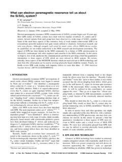
6 ;. END Component ;. BEGIN. U1 : barney PORT MAP(clk => clk, enable => enbl, adv => adv, clear => clear, outa => pulse, ask_me => ask_me );. U2 : elmo PORT MAP(ask_me => ask_me, go => open_door, clear => clear );. END struct;. Component Instantiation 6. The code for represents the following block diagram. arthur barney clk clk outa pulse enbl enable elmo adv adv ask_me ask_me ask_me go open_door clear clear U1. U2. clear VHDL is by nature verbose. Before using a Component within another Component , it must be declared with the Component declaration. The body of the Component declaration is nearly an exact copy of the entity declaration from that module's .vhd file. Thus, quick and efficient copy and paste with emacs/vi can let you insert the Component declarations in seconds. Use of multiple windows or using the split window feature in vi can really speed code writing up. Component Instantiation 7. Named vs.
7 Positional Association As previously mentioned, pin/signal pairs used with a PORT MAP may be associated by position. For example, U1 : mux21 PORT MAP(a_input,b_input,sel(0),temp0);. This form is not preferred because any change in the port list (it often happens in the design phase) will be difficult to incorporate. Try doing it for entities with 50 or more signals and you'll begin to appreciate the point. For example, some real Component Instantiation 8. Sample PORT MAP (w/named association). dramfifo_0: dramfifo PORT MAP( reg_data => reg_data , dram_state_ps => dram_state_ps , dram_cnt_ps => dram_cnt_ps , dram_cycle_type => dram_cycle_type , addr_adv => addr_adv , line_shift => line_shift , cycle_start => cycle_start , done => done , any_rdgnt => any_rdgnt , any_wrgnt => any_wrgnt , test_mode => test_mode , scl_ratio_ack => scl_ratio_ack , y_wrptrlo_wen => y_wrptrlo_wen , y_wrptrhi_wen => y_wrptrhi_wen , u_wrptrlo_wen => u_wrptrlo_wen , u_wrptrhi_wen => u_wrptrhi_wen , v_wrptrlo_wen => v_wrptrlo_wen , v_wrptrhi_wen => v_wrptrhi_wen , wrcntrlo_wen => wrcntrlo_wen , wrcntrhi_wen => wrcntrhi_wen , y_rdptrlo_wen => y_rdptrlo_wen , y_rdptrhi_wen => y_rdptrhi_wen , u_rdptrlo_wen => u_rdptrlo_wen , u_rdptrhi_wen => u_rdptrhi_wen , v_rdptrlo_wen => v_rdptrlo_wen , v_rdptrhi_wen => v_rdptrhi_wen , rdcntrlo_wen => rdcntrlo_wen , rdcntrhi_wen => rdcntrhi_wen , yeol_cntr_wen => yeol_cntr_wen.)
8 Ueol_cntr_wen => ueol_cntr_wen , veol_cntr_wen => veol_cntr_wen , line_length_wen => line_length_wen , ptr_rollbit_wen => ptr_rollbit_wen , clk_24 => clk_24 , clk_48 => clk_48 , rst_24 => rst_24 , rst_48 => rst_48 , s_capt_en => s_capt_en , vsync => vsync , even_fld => even_fld , qual_hsync => qual_hsync , sr_sel => sr_sel , current_sr => current_sr , allow_rdreq => allow_rdreq , allow_wrreq => allow_wrreq , wr_addr => wr_addr , rd_addr => rd_addr , last_line_segment => last_line_segment, start_of_video => start_of_video , end_of_video => end_of_video , line_length_rback => line_length_rback, dcu_status => dcu_status);. Component Instantiation 9. Same PORT MAP (w/positional association). -- dram fifo address control dramfifo_0: dramfifo PORT MAP(reg_data, dram_state_ps, dram_cnt_ps, dram_cycle_type, addr_adv, line_shift, cycle_start, done, any_rdgnt, any_wrgnt, test_mode, scl_ratio_ack, y_wrptrlo_wen, y_wrptrhi_wen, u_wrptrlo_wen, u_wrptrhi_wen, v_wrptrlo_wen, v_wrptrhi_wen, wrcntrlo_wen, wrcntrhi_wen, y_rdptrlo_wen, y_rdptrhi_wen, u_rdptrlo_wen, u_rdptrhi_wen, v_rdptrlo_wen, v_rdptrhi_wen, rdcntrlo_wen, rdcntrhi_wen, yeol_cntr_wen, ueol_cntr_wen, veol_cntr_wen, line_length_wen, ptr_rollbit_wen, clk_24, clk_48, rst_24, rst_48, s_capt_en, vsync, even_fld, qual_hsync, sr_sel, current_sr, allow_rdreq, allow_wrreq, wr_addr, rd_addr, last_line_segment, start_of_video, end_of_video, line_length_rback, dcu_status).
9 Now, lets say you need to add an extra signal in the module dramfifo. You want to put it just after ueol_cntr_wen. But let's say your signals do not necessarily have the same names as the pins. This means you would have to manually count through the list of signals to find out where to put the new one in the port map in exactly the same order. How would you know for sure its in the right position? Count through the list again! Do you have time to do this? Does your boss have the time for you to waste? Use named association. This is another case where efficient use of a programming editor will enable you to produce more readable and more likely correct code. Component Instantiation 10. Association lists - Some last Suppose you have a module that is a four to one mux, but you only need three inputs. What do you do with the unused input? What about unused outputs? If the module you are instantiating has a defined default port value, the keyword OPEN can be used to allow the input to be assigned the default port value.
10 Thus the entity for a 4:1 mux with a defined default port value would look like this: ENTITY mux41 IS. PORT(. a0 : IN STD_LOGIC := 0'; --input a0 can be left OPEN. a1 : IN STD_LOGIC := 0'; --input a1 can be left OPEN. a2 : IN STD_LOGIC := 0'; --input a2 can be left OPEN. a3 : IN STD_LOGIC := 0'; --input a3 can be left OPEN. sel : IN STD_LOGIC_VECTOR(1 DOWNTO 0); --sel input z_out : OUT STD_LOGIC --data out );. END mux21;. I don't recommend this as it hides functionality. The initalization expression := 0' in the port declaration states that the input signals a_input , b_input, c_input and d_input will take on the default value'0'. if they are left unconnected by a Component Instantiation . Thus we could instantiate the 4:1 mux as follows: U1 : mux41 PORT MAP(a0 => a_input, a1 => b_input, a2 => c_input, a3 => OPEN, --a3 is assigned the value 0'. sel => sel_input), z_out => data_out);. Unconnected output ports are also designated by using the keyword OPEN.