Transcription of Compumotor p/n 88-014027-01 A
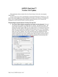
1 Compumotor DivisionParker Hannifin Corporationp/n 88- 014027 -01 ACompumotorZETA DriveInstallation GuideZETAZETADRIVEDRIVEC ompumotorMOTORINTERLOCKINTERLOCKA A CENTER TAPCENTER TAPA+A+A-A-EARTHEARTHB+B+B-B-B B CENTER TAPCENTER TAPINTERLOCKINTERLOCKPOWERPOWERSTEPSTEPO VER TEMPOVER TEMPMOTOR FAULTMOTOR FAULT40123567 ELECTRONICELECTRONICVISCOSITYVISCOSITY04 81212 ACTIVEACTIVEDAMPINGDAMPINGAC POWER95-132 VAC95-132 VAC50/60 Hz50/60 HzINDEXERRESET+RESET+RESET RESET FLT CFLT CFLT EFLT ESD -SD -SD +SD +DIR -DIR -DIR +DIR +STEP -STEP -STEP +STEP +1111232392121171716161515214141To ensure that the equipment described in this user guide, as well as all the equipment connected to and used with it, operates satisfactorily and safely, all applicable local and national codes that apply to installing and operating the equipment must be followed. Since codes can vary geographically and can change with time, it is the user's responsibility to identify and comply with the applicable standards and codes.
2 WARNING: Failure to comply with applicable codes and standards can result in damage to equipment and/or serious injury to who are to install and operate the equipment should study this user guide and all referenced documentation prior to installation and/or operation of the equipment. In no event will the provider of the equipment be liable for any incidental, consequential, or special damages of any kind or nature whatsoever, including but not limited to lost profits arising from or in any way connected with the use of this user guide or the equipment. Compumotor Division of Parker Hannifin Corporation, 1995 All Rights Reserved The information in this user guide, including any apparatus, methods, techniques, and concepts described herein, are the proprietary property of Parker Compumotor or its licensors, and may not be copied, disclosed, or used for any purpose not expressly authorized by the owner Parker Compumotor constantly strives to improve all of its products, we reserve the right to change this user guide and equipment mentioned therein at any time without America: Compumotor Division of Parker Hannifin5500 Business Park DriveRohnert Park, CA 94928 Telephone: (800) 358-9070 Fax: (707) 584-8015 BBS: (707) 584-4059 Europe:Parker Digiplan21 Balena ClosePoole, DorsetEngland BH17 7 DXTelephone: 0202-690911 Fax: 0202-600820 User InformationTechnical Assistance Contact your local Automation Technology Center, of ContentsChapter 1 Introduction.
3 1 Description ..2 DIP & Technologies in the ZETA Drive .. 3 The ZETA Name .. 3 ZETA Motors .. 4 Chapter 2 Installation .. 5 What You Should Have (ship kit) .. 6 Precautions .. 6 Installation Overview .. 6 Quick Test ..8 Installation .. 10 1 SELECT A 2 CHOOSE SERIES OR PARALLEL MOTOR 12 3 SET DIP 14 4 CONNECT AN INDEXER INPUTS & 17 5 MATCH THE DRIVE TO THE 20 6 MOUNT THE 22 7 MOUNT THE 24 8 CONNECT THE MOTOR TO THE LOAD 25 9 CONNECT AC TEST THE 2711 RESONANCE, RINGING AND DAMPING DISCUSSION AND 2812 DAMPING IN THE ZETA VISCOSITY (EV) .. 3113 SET ROTARY SWITCHES TO 3214 CONFIGURE ACTIVE CONFIGURE ELECTRONIC VISCOSITY (EV) .. 3416 RECORD YOUR SYSTEM S CONFIGURATION 34 Chapter 3 Troubleshooting ..35 Troubleshooting Basics ..36 Diagnostic LEDs .. 36 Protective Circuits .. 36 OVERTEMPERATURE CIRCUIT Test ..37 Anti-Resonance Disable ..37 Technical Support .. 37 Product Return Procedure .. 38 Appendix Using Non- Compumotor Motors.
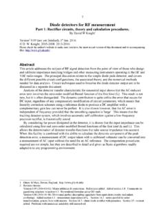
4 39 Index .. 45 Introduction11 IntroductionIN THIS CHAPTER ZETA Drive Description Anti-Resonance Active Damping Electronic ViscosityCHAPTER ONE2 ZETA Drive User GuideZETA DRIVE DESCRIPTIONThe ZETA Drive is a microstepping drive that runs two-phase step operates directly from 120 VAC power; no separate DC power supply ortransformer is typical system is shown TEMPOVER TEMPMOTOR FAULTMOTOR FAULT40123567 ELECTRONICELECTRONICVISCOSITYVISCOSITY04 81212 ACTIVEACTIVEDAMPINGDAMPINGAC POWERAC POWER95-132 VAC95-132 VAC50/60 Hz50/60 HzINDEXERINDEXERMOTORMOTORINTERLOCKINTER LOCKA A CENTER TAPCENTER TAPA+A+A-A-EARTHEARTHB+B+B-B-B B CENTER TAPCENTER TAPINTERLOCKINTERLOCKTo AC PowerSourceIndexerMotorZETAD rive1111232392121171716161515214141 RESET+RESET+RESET RESET FLT CFLT CFLT EFLT ESD -SD -SD +SD +DIR -DIR -DIR +DIR +STEP -STEP -STEP +STEP +System ComponentsThe indexer sends step and direction signals to the drive. For each steppulse it receives, the drive will commutate the motor to increment rotorposition.
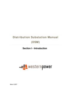
5 This is shown in the next DriveMotorMotorCurrentsStepPulsesHigh LevelCommandsHost Computeror ProgrammableControllerBlock Diagram of ZETA SystemThe host computer or programmable controller may or may not be neces-sary, depending upon the indexer s motor can be wired in series or parallel; the amount of current thedrive sends to the motor is set by DIP SWITCHESDIP switches are located on top of the ZETA drive, behind a removablemetal cover. During the installation procedure, the user sets these DIPswitches to scale the drive for motor current, resolution, waveform, andother functions. Introduction3 INPUT & OUTPUTAll communications with the indexer take place through the ZETA Drive s25-pin D-connector. Available inputs and outputs are: Step Input Direction Input Shutdown Input Fault Output Reset Input Clockwise/Counterclockwise InputPOTENTIOMETERST hree potentiometers are located on top of the ZETA Drive, next to the DIPswitches. The potentiometers are used to adjust the drive s electricalcharacteristics to match the motor s individual TECHNOLOGIES IN THE ZETA DRIVEAll step motors are subject to resonance, and to ringing after quick tran-sient moves.
6 The ZETA Drive has three unique circuits that can dampresonance and is a general purpose damping circuit that works automatically. Noconfiguration is necessary. Anti-resonance provides aggressive and effec-tive DAMPINGThis is an extremely powerful damping circuit. The user sets four DIPswitches and one rotary switch on the drive, to optimize active dampingfor a specific motor and and active damping work at speeds greater than threerevolutions per VISCOSITY (EV)This circuit provides damping at speeds from rest up to three revolutionsper second. The user sets one rotary switch on the drive, to optimize EVfor a particular application. EV can reduce settling time at the end of amove, which can lead to increased machine ZETA NAME In the equation that describes the transfer function of a step motor, theGreek symbol (zeta) is used to represent the damping ratio. Becauseour drive has such sophisticated and unique damping capabilities, wedecided to name it the ZETA Drive User GuideZETA MOTORSZETA Series motors are available from Compumotor for use with the ZETAD rive.
7 These motors are designed to match the drive s high FAMILY OF PRODUCTSThe ZETA Drive is completely compatible with Compumotor s broad rangeof microstepper indexers (single-axis and multi-axis) and motion controlproducts. Installation52 InstallationIN THIS CHAPTER Product Ship Kit List Quick Test Motor Selection and Wiring Drive Configuration DIP Switches, I/O, Potentiometers Mounting the Drive and Motor; Attaching the Load Testing the Installation Active Damping and Electronic Viscosity ConfigurationCHAPTER TWO6 ZETA Drive User GuideWHAT YOU SHOULD HAVE (SHIP KIT) If you ordered a ZETA Drive Only (no motor), you should have:PartPart NumberZETA DriveZETA4 Power Cable feet ( M) in length44-014768-01 Motor Connector 9 pin43-008755-01 ZETA Drive Installation Guide88- 014027 -01If you ordered a ZETA System (drive and motor), you should receive all ofthe above, plus one of the following ZETA Motors:PartPart NumberZETA MotorZETA57-51 ZETA83-62 ZETA57-83 ZETA83-93 ZETA57-102 ZETA83-135 The motor has a permanently attached cable, 10 feet (3 m) long.
8 Themotor connector is wired to the cable at the prevent injuries to personnel and damage to equipment, observe thefollowing guidelines: Never probe the drive. Hazardous voltages are present within the drive. Never open the drive. Opening the drive will void the warranty. Never increase the current setting to a value greater than that specified forthe motor you are using. Excessive current may cause motor overheatingand OVERVIEWT opics in this chapter are arranged to lead you through the installationprocess in a step by step manner. Complete each step before proceedingto the order of topics in the installation procedure is: Quick Test Motor selection, specifications, and speed/torque curves Motor wiring series vs. parallel DIP switch configuration Indexer connections and 25 pin D-connector input/output schematic Drive/Motor matching procedure Drive mounting Motor mounting Connecting the load Connecting AC power Testing the installation Resonance, ringing, and damping discussion and theory Active Damping and Anti-Resonance configuration Electronic Viscosity configuration Installation7 INSTALLATION PROCEDUREIn the following installation procedure, we assume you are using a ZETAM otor with your ZETA drive.
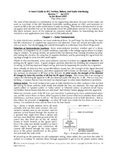
9 If you are using a non- Compumotor motor,consult the Appendix at the end of this user guide for information youmay need during the following installation next drawing shows locations and names of the various connectors,switches, etc., that you will encounter during the installation A CENTER TAPCENTER TAPA+A+A-A-EARTHEARTHB+B+B-B-B B CENTER TAPCENTER TAPINTERLOCKINTERLOCKPOWERPOWERSTEPSTEPO VER TEMPOVER TEMPMOTOR FAULTMOTOR FAULT40123567 ELECTRONICELECTRONICVISCOSITYVISCOSITY04 81212 ACTIVEACTIVEDAMPINGDAMPINGAC POWERAC POWER95-132 VAC95-132 VAC50/60 Hz50/60 HzRESET+RESET+RESET RESET FLT CFLT CFLT EFLT ESD -SD -SD +SD +DIR -DIR -DIR +DIR +STEP -STEP -STEP +STEP +1111232392121171716161515214141 INDEXERINDEXERZETADRIVEDRIVEC ompumotorMOTORINTERLOCKINTERLOCKA A CENTER TAPCENTER TAPA+A+A-A-EARTHEARTHB+B+B-B-B B CENTER TAPCENTER TAPINTERLOCKINTERLOCKPOWERPOWERSTEPSTEPO VER TEMPOVER TEMPMOTOR FAULTMOTOR FAULT40123567 ELECTRONICELECTRONICVISCOSITYVISCOSITY04 81212 ACTIVEACTIVEDAMPINGDAMPINGAC POWER95-132 VAC95-132 VAC50/60 Hz50/60 HzINDEXERDIP SwitchesBalance &Offset PotentiometersIndexer ConnectorStatus LEDsMotor ConnectorActive DampingRotary SwitchElectronic ViscosityRotary SwitchPower
10 ConnectorHeatsink11112323921211717161615 15214141 RESET+RESET+RESET RESET FLT CFLT CFLT EFLT ESD SD SD +SD +DIR DIR DIR +DIR +STEP STEP STEP +STEP +ZETA Drive Component Locations8 ZETA Drive User GuideQUICK TESTF ollow this procedure to have your ZETA drive perform its automatic testfunction. Once you set DIP switches, connect the motor, and connect ACpower, the automatic test will begin the motor shaft will turn in thecounterclockwise direction until you remove power. This will verify thatthe drive, motor, and motor cable work properly as a TEMPOVER TEMPMOTOR FAULTMOTOR FAULT40123567 ELECTRONICELECTRONICVISCOSITYVISCOSITY04 81212 ACTIVEACTIVEDAMPINGDAMPINGAC POWERAC POWER95-132 VAC95-132 VAC50/60 Hz50/60 HzINDEXERINDEXERMOTORMOTORINTERLOCKINTER LOCKA A CENTER TAPCENTER TAPA+A+A-A-EARTHEARTHB+B+B-B-B B CENTER TAPCENTER TAPINTERLOCKINTERLOCKTo AC PowerSourceMotorCounterclockwise(Negativ e) Shaft RotationZETAD rive1111232392121171716161515214141 RESET+RESET+RESET RESET FLT CFLT CFLT EFLT ESD -SD -SD +SD +DIR -DIR -DIR +DIR +STEP -STEP -STEP +STEP +Quick Test SetupThis is a bench top procedure as the drawing shows, you can perform itbefore you connect an indexer, mount the drive, or mount the motor.