Transcription of COMPUTER INSTALL SOFTWARE ON Back-UPS User’s …
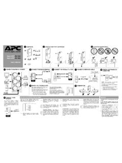
1 TVSS GNDM odem/Fax/PhoneWallOutletData PortCircuit BreakerPush to ResetInput: 220-240V~, 7A, 50-60Hz10/100 Base-T / VOIPBATTERYBACKUPSURGE ONLY220-240V~, 3A, 50-60Hz, 540W220-240V~, , 50-60Hz, 540 WCONNECT TVSSBack-UPS RS 800 User s Manual2 OPERATING ENVIRONMENT3 CONNECT EQUIPMENT / POWERM onitorPrinter or ScannerFAXE xternal Disk orCD / DVD DriveComputer4 Phone JackCONNECT PHONE/MODEM/FAX6 CONNECT 10/100 Base-T or VOIP5To COMPUTER USBPortCONNECT INTERFACEC omputer8 INSTALL SOFTWARE ON COMPUTERT here are four status indicators (lights) on the frontpanel of the Back-UPS (On Line, On battery , Overload,and Replace battery ).On Line (green) - is lit whenever utility power ispowering the battery Backup battery (yellow) - is lit whenever the battery ofthe Back-UPS is powering equipment connected to theBattery Backup Beeps Every 30 Seconds - this alarm issounded whenever the Back-UPS is running OnBattery.
2 Consider saving work in (red) - is lit whenever power demand hasexceeded the capacity of the Tone - this alarm is soundedwhenever the battery Backup outlets Breaker - the circuit breaker buttonlocated on the rear panel of the Back-UPS willstick out if an overload condition forces the Back-UPS to disconnect itself from utility power. If thebutton sticks out, disconnect non-essentialequipment. Reset the circuit breaker by pushingthe button battery (red) - is lit whenever the battery isnear the end of its useful life, or if the battery is not con-nected (see above). A battery that is near the end of its use-ful life has insufficient run-time and should be for 1 Minute Every 5 Hours - thisalarm is sounded whenever the battery has failedthe automatic diagnostic : Allow the Back-UPS to charge for a full eight (8)hours prior to the front panel Power ON/OFF switch and observethat the following events occur after pressing andreleasing the switch: The green On Line indicator flashes.
3 The yellow On battery indicator lights while a Self-Test is being performed. When Self-Test has successfully completed, only the green On Line indicator will be lit. If the internal battery cartridge is not connected (see Step 1 above), the green On Line indicator and red Replace battery indicators will light. The Back-UPS will also emit a chirping Beeping - this alarm is soundedwhenever a low battery condition is run-time is very low. Promptly save anywork in progress and exit all open the operating system, COMPUTER andthe : Macintosh Users - for full USB performance,use OS or Autoplay is not enabled on the COMPUTER , proceedas follows:1. On the COMPUTER desktop of the display, double-click on My Double-click on the CD-ROM drive icon andfollow the on-screen ON THE back -UPS9 GROUNDThe Back-UPS features a transientvoltage surge-suppression (TVSS)screw for connecting the groundlead on additional surgesuppression devices such asnetwork and data line Data LineTVSSF ollow LineOn BatteryOverloadReplace BatteryRJ-45 USBSTATUS INDICATORS AND ALARMSCABLETVSS GNDM odem/Fax/PhoneWallOutletData PortTVSS GNDM odem/Fax/PhoneWallOutletCONNECT battery CARTRIDGE1 ComputerModem PortModem/WallOutletData Port10/100 Base-T / VOIPN etwork JackComputerNetwork PortTo 220-240 VAC, 50-60 HzYour ComputerPower Cord0 - 40oC (32 - 104oF) 30 cm w w SPECIFICATIONSItemSpecificationOn-line Input Voltage Range(default settings)
4 175 - 295 VacAutomatic Voltage Regulation (AVR)+12%On-line Frequency Range47 - 63 Hz (autosensing)On- battery WaveshapeStepped Sine WaveMaximum Load800 VA - 540 WTypical Recharge Time8 HoursOperating Temperature0o to 40oC(32o to 104oF)Storage Temperature-5o to 45oC(23o to 113oF)Operating / Storage Relative Humidity0 to 95% non-condensingSize (H x W x D)23 x 10 x 32 cm(9 x 4 x inch) kg ( lbs)Shipping kg (22 lbs)EMI ClassificationEN 50091-1, EN 60950, EN 50091-2, EN 61000-3-2, EN 6100-3-3,EN 55022 Class BOn battery Run-TimeSee TROUBLESHOOTINGP roblem Possible CauseCorrective ActionBack-UPS will not switch not connected to AC power source. Ensure the Back-UPS is securely connected to an AC circuit breaker tripped . Disconnect non-essential equipment from the Back-UPS . Reset(push in) the rear panel circuit breaker. Switch on the back -UPSand plug in devices one at a time.
5 If the circuit breaker tripsagain, disconnect the device that caused the breaker to input voltage quality is out of adjusting the transfer voltage and sensitivity. SeeTransfer Voltage and Sensitivity battery cartridge is not battery cartridge (see Connect battery Cartridge). Back-UPS does not power essential equipment during an outage. Equipment plugged into a Surge Only outlet. Unplug device from 'Surge Only' outlet and move to a 'BatteryBackup' operates on battery although utility power circuit breaker tripped . Disconnect non-essential equipment from the Back-UPS . Reset(push in) the rear panel circuit breaker. Switch the Back-UPS onand plug equipment in one-at-a-time. If the circuit breaker tripsagain, disconnect the device that caused the breaker to input voltage quality is out of adjusting the transfer voltage and sensitivity.
6 SeeTransfer Voltage and Sensitivity does not provide expected backup is heavily loaded. Unplug non-essential equipment (printers, scanners, etc) fromthe battery Backup outlets and plug into 'Surge Only' battery cartridge is discharged due to recent power outage and has not had time to recharge. Charge the battery cartridge for 8 hours. Back-UPS runtime isreduced until the battery cartridge is fully charged. battery has reached the end of its battery cartridge (see Order Replacement BatteryCartridge).Red Replace battery indicator is flashing. Green On Line indicator is battery cartridge is not battery cartridge (see Connect battery Cartridge).Red Replace battery indicator is has reached the end of its the battery cartridge (see Order Replacement BatteryCartridge).Red Overload indicator is on or equipment is drawing more power than the Back-UPS can one or more equipment power plugs from battery Backupoutlets to Surge Only On Line indicator is on and all other front panel indicators are UPS APC Technical Support (see Contact Information).
7 SERVICEIf the Back-UPS arrived damaged, notify the the Back-UPS requires service, do not return it to the dealer. The followingsteps should be the Troubleshooting section to eliminate common the problem persists, go to the problem still persists, contact APC Technical the Back-UPS model number, serial number and date of purchaseavailable. Be prepared to troubleshoot the problem with an APC TechnicalSupport representative. If this is not successful, APC will issue a ReturnMerchandise Authorization (RMA) number and a shipping INFORMATIONT echnical / / + WARRANTYThe standard warranty is two (2) years from the date of purchase. APC s standardprocedure is to replace the original unit with a factory reconditioned who must have the original unit back due to the assignment of assettags and set depreciation schedules must declare such a need at first contact withan APC Technical Support representative.
8 APC will ship the replacement unitonce the defective unit has been received by the repair department, or cross-shipupon the receipt of a valid credit card number. The customer pays for shipping theunit to APC. APC pays ground freight transportation costs to ship the replacementunit to the VOLTAGE AND SENSITIVITYORDER REPLACEMENT battery CARTRIDGEThe battery cartridge typically lasts 3-6 years, shorter if subjected to frequent outages or elevated temperatures. Order part number recycle spent battery 1/04 Copyright 2004 American Power Conversion All rights and Back-UPS are registered trademarks of American Power other trademarks are the property of their respective battery CARTRIDGE1234In situations where the Back-UPS or connected equipment appears too sensitiveto input voltage, it may be necessary to adjust the transfer voltage.
9 This is asimple task requiring use of the front panel pushbutton. To adjust the transfervoltage, proceed as follows:1. Plug the Back-UPS into the utility power source. The Back-UPS will be in aStandby Mode (no indicators lit).2. Press the front panel pushbutton fully inward for 10 seconds. All indicatorson the Back-UPS will flash to acknowledge going into Programming The Back-UPS will then indicate its current Sensitivity Setting, as shown inthe following To select the Low Sensitivity setting, press the pushbutton until the yellowindicator is To select the Medium Sensitivity setting, press the pushbutton until theyellow and red indicators (second and third from the top) are To select the High Sensitivity setting, press the pushbutton until yellow andboth red indicators (bottom three) are To exit without changing the Sensitivity Setting, press the pushbutton untilthe green indicator is Once in Programming Mode, if the pushbutton is not pressed within 5seconds, the Back-UPS will exit Programming Mode.
10 All indicators VoltageRange(for utility operation)Use When1(yellow)Low156 - 300 Vac Input voltage is extremely low or high. Not recommended for COMPUTER (yellow, and red)Medium(factory default)176 - 288 VacBack-UPS frequently goes On (yellow, red, and red)High176 - 278 Vac Connected equipment is sensitive to voltage fluctuations (recommended).