Transcription of CONA S - ARI Armaturen
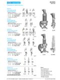
1 A W H Armaturen - WERK halle GMBH halle A member of the ARI groupEdition 04/18 - Data subject to alteration - Regularly updated data on !Ball float steam trap PN16 / PN40- with flanges (Fig. )- with screwed sockets (Fig. )- with socket weld ends (Fig. )- with butt weld ends (Fig. )Grey cast iron SG iron Forged steel/ Cast steelStainless steelFig. 631 Page 2 Ball float steam trap PN63 / PN100- with flanges (Fig. )- with socket weld ends (Fig. )- with butt weld ends (Fig. )High temperature steel Fig. 631 Page 6 Ball float steam trap PN160- with flanges (Fig. )- with socket weld ends (Fig. )- with butt weld ends (Fig. )Angle pattern design:- with flanges (Fig. )- with butt weld ends (Fig. )High temperature steel Fig. 631 / Fig. 632 Page 8 Ball float steam trap PN16 / PN40- with flanges R4-P (Fig.)
2 - with flanges (Fig. )Forged steel/ Grey cast ironForged steel/Cast steel Stainless steelFig. 633 / Fig. 639 Page 10 Page 12 Ball float steam trap PN16 / PN25PN40- with flanges (Fig. )Angle pattern design: - with flanges (Fig. )SteelFig. 637 / Fig. 638 Page 14 Ball float steam trap for drainage of water from compressed air and gas systems(acc. to PED 2014/68/EU fluid group 2)PN16 / PN40- with flanges (Fig. )- with screwed sockets (Fig. )- with socket weld ends (Fig. )- with butt weld ends (Fig. )Grey cast iron SG iron Forged steel/ Cast steel Stainless steel Fig. 630 Page 16 CONA SBall float steam trapFeatures: Back pressure-free condensate discharge even at extreme pressure- and quantity fluctuations Controller with integrated automatic ventilation (except Fig. 630) Robust and insensitive to waterhammer Non return protection (except Fig.)
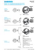
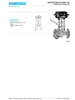
3 633/637/638) Union for pressure compension line and bypass possible On-site change of the installation position is possible according to the operating instructions (except Fig. 633/637/638) The controller maybe changed without disturbing the pipe workFig. vertical installation Ball float steam trapFig. horizontal installation2 Edition 04/18 - Data subject to alteration - Regularly updated data on !Ball float steam trap (Grey cast iron, SG iron, Forged steel/Cast steel, Stainless steel) Fig. with flanges - vertical installationFig. with flanges - horizontal installationCONA S 631PN16 / PN40 - DN15-100 FigureNominal pressureMaterialNominal diameter / NPSO perating pressure PSInlet temperature TSallowable differential pressure PMXfor : EN-JL104015 - 50 / 1/2" - 2"12,8 barg200 C2 bar4 bar8 bar13 barR2 R4 R8 R13 DN40 / NPS 1 1/2": R2-S R4-S R8-S R13-S9,6 barg300 : EN-JS104915 - 50 / 1/2" - 2"32 barg250 C2 bar4 bar8 bar13 bar PN40:22 bar32 barR2 R4 R8 R13 PN40:R22 R32 DN40 / NPS 1 1/2": R2-S R4-S R8-S R13-S22 barg350 : / Hood: +N15 - 100 / 1/2" - 4"32 barg250 C21 barg400 : / - 100 / 1/2" - 4"32 barg250 C28 barg300 CFor ANSI versions refer to data sheet cona s -ANSIT ypes of connection Other types of connection on request.
4 Flanges ..1 _____acc. to DIN EN 1092-2 (EN-JL1040) and DIN EN 1092-1 ( , ) Screwed sockets ..2 ___Rp thread acc. to DIN EN 10226-1 or NPT thread acc. to ANSI Socket weld ends ..3 ___acc. to DIN EN 12760 Butt weld ends ..4 _____ Weld preparation acc. to EN ISO 9692 identification No. and (Note restriction on operating pressure / inlet temperature depending to design!)Features Ball float steam trap with level control for the condensate-discharge from all kinds of steam systems Rapid system start-up due to thermostatic control element Inside strainer Body with flanged hood Non return protection The controller maybe changed without disturbing the pipe work On-site change of the installation position is possible according to the operating instructionsMounting position Standard:verticalPlease indicate when ordering!
5 Refer to: Information about the different installation positions (Page 21) On-site change of the installation position is possible according to the operating instructions. Optional:horizontal with inlet from right or leftOptions Air vent - (Pos. 51) or blow down valve (Pos. 46), manual operatedFig. with screwed socketsFig. with socket weld endsFig. with butt weld ends3 Edition 04/18 - Data subject to alteration - Regularly updated data on !Types of connectionFlangesScrewed sockets 1) Socket weld ends 2)Butt weld ends 2)DN(mm)15 2025405065 2)80 2)100 2)15 20254050 1)15 20254050 NPS(inch)1/2"3/4"1"1 1/2"2"2 1/2" 2)3" 2)4" 2)1/2"3/4"1"1 1/2"2" 1)1/2"3/4"1"1 1/2"2" 1) DN50 (2 ) not in EN-JL/EN-JS 2) not in EN-JL / EN-JS Face-to-face acc. to data sheet resp. customer requestL(mm)1501501602302302903103501501 50160210210160160160250250 Dimensions Standard-flange dimensions refer to page (mm)162162193274274274274274162162193274 274162162193274274H1(mm)8787107157157157 15715787871071571578787107157157B (EN-JS1049)(mm)215215245289289------2152 15245289------------B (Steel)(mm)21721724929229229229229217017 0197292292170170197292292B1(mm)114114135 1941941941941941141141351941941141141351 94194S(mm)180180200300300300300300180180 200300300180180200300300S1(mm)1501501802 0020020020020015015018020020015015018020 0200 Weights Fig.
6 631 (approx.)(kg)8,18,312,128,529,1313336,57 ,57,59,723,824,37,18,110,224,825, , EN-JL1040EN-GJS-400-18U-LT, EN-JS1049P250 GH, , ring CUA416 HoodEN-GJL-250, EN-JL1040EN-GJS-400-18U-LT, EN-JS1049GP240GH+N, +NGX5 CrNi19-10, Graphite (CrNi laminated with graphite)24xController, cpl. X5 CrNi18-10, / TB102/85 (corrosion resistant bimetal) , head screwA2-70 / 5-7, 5-7, < DN40: A4-80 DN40: X6 CrNiTi18-10, down valve, cpl. X6 CrNiTi18-10, ring CUA450 Plug (M14x1,5) C35E, , air vent valve X8 CrNiS18-9, Spare partsInformation / restriction of technical rules need to be observed! Resistance and fitness must be verified (contact manufacturer for information, refer to Product overview and Resistance list).Operating and installation instructions can be downloaded at S 631 PN16 / PN40 - DN15-100 Options Air vent - (Pos.)
7 51) or blow down valve (Pos. 46), manual operated4 Edition 04/18 - Data subject to alteration - Regularly updated data on ! cona s 631 PN16 / PN40 - DN15-100 Capacity chartStandard R22 and R32 DN15 - DN100 The capacity chart shows the maximum flow quantities of hot condensate for the different controllers and steam trap sizesIn commen, the steam traps are fitted out with an controller as shown in the flow diagrams of this page acc. to the differential pressures and flow very large flow rates with low differential pressures, steam traps at sizes DN40 up to DN100 can be fitted out with a super-controllerThe maximum flow quantity of cold condensate at about 20 C can be determined by multiplication of the appropriate factor F (in the scale below the diagrams) with the hot condensate quantity determined by the capacity chart.
8 (Factor F is related to the differential pressure)Standard R2 to R13DN15 - DN100 The capacity chart shows the maximum flow quantities of hot condensate for the different controllers and steam trap sizesIn commen, the steam traps are fitted out with an controller as shown in the flow diagrams of this page acc. to the differential pressures and flow very large flow rates with low differential pressures, steam traps at sizes DN40 up to DN100 can be fitted out with a super-controllerThe maximum flow quantity of cold condensate at about 20 C can be determined by multiplication of the appropriate factor F (in the scale below the diagrams) with the hot condensate quantity determined by the capacity chart. (Factor F is related to the differential pressure)Flow (kg/h)Differential pressure considering drainage into atmosphere (bar)Flow (kg/h)Differential pressure considering drainage into atmosphere (bar)5 Edition 04/18 - Data subject to alteration - Regularly updated data on !
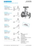
9 cona s 631 PN16 / PN40 - DN15-100 Capacity chartSpecial design: Super-controller for very large flow rates with low differential pressuresR2-S to R13-SDN 40 - 100 The capacity chart shows the maximum flow quantities of hot condensate for the Super-controller maximum flow quantity of cold condensate at about 20 C can be determined by multiplication of the appropriate factor F (in the scale below the diagrams) with the hot condensate quantity determined by the capacity chart. (Factor F is related to the differential pressure)Flow (kg/h)Differential pressure considering drainage into atmosphere (bar)6 Edition 04/18 - Data subject to alteration - Regularly updated data on !Ball float steam trap (High temperature steel) Fig. with flanges - vertical installation (PN100)Fig. with flanges - horizontal installation (PN100) cona s 631 PN63 / PN100 - DN15-50 FigureNominal pressureMaterialNominal diam.
10 / NPSO perating pressure PSInlet temperature TSallowable differential pressure PMXfor : 16Mo3 / Hood: G17 CrMo5-515 - 50 / 1/2" - 2"56 barg300 C50 barR5050 barg350 C45 barg450 : 16Mo3 / Hood: G17 CrMo5-515 - 50 / 1/2" - 2"64 barg400 C64 bar50 barR64 R5050 barg450 : 13 CrMo4-5 / Hood: G17 CrMo515 - 50 / 1/2" - 2"80 barg480 C80 bar64 bar50 barR80 R64R5064 barg504 C50 barg515 C30 barg525 CFor ANSI versions refer to data sheet cona s -ANSIT ypes of connection Other types of connection on request. Flanges ..1 _____acc. to DIN EN 1092-1 Butt weld ends ..4 _____ Weld preparation acc. to EN ISO 9692 identification No. and (Note restriction on operating pressure / inlet temperature depending to design!)Features Ball float steam trap with level control for the condensate-discharge from all kinds of steam systems Rapid system start-up due to thermostatic control element (for condensate with temperatures 100 C) Inside strainer Body with flanged hood Non return protection The controller maybe changed without disturbing the pipe workMounting position Standard:verticalPlease indicate when ordering!