Transcription of Conceptual Design Modeling in Autodesk Revit …
1 Autodesk Revit Architecture 2010 Conceptual Design Modeling in Autodesk Revit Architecture 2010 In building Design , visualizing a form in the earliest stages enhances a designer s ability to communicate ideas; and the ability to analyze and evaluate these forms yields an advantage in predicting and optimizing the real-world performance of the built project. These attributes form a core value of the building information Modeling (BIM) process, for which Autodesk Revit Architecture software is purpose-built to support. With the release of Revit Architecture 2010, users now have access to a robust collection of easy-to-use Modeling tools for quick and precise Design conceptualization, visualization, and communication. This release supports several new Modeling paradigms, including intuitive direct manipulation, robust freeform Modeling , and bidirectional parametric control. In addition, some highly specialized patterning and panelization techniques are now more readily accessible for users of all skill levels.
2 Using a speculative urban high-rise project as the model for exploration, this white paper details how CASE Design , a Design technology consultancy based in New York City, utilized the new Conceptual Design tools in Revit Architecture to more easily create massing designs; explore Design alternatives based on qualitative and quantitative feedback; and address various environmental, constructability, and aesthetic concerns that arose during project realization. In order to clearly address the new Parametric Massing Design and Custom Panelization Modeling environments introduced with this release, this white paper has been divided into two sections. In the Parametric Massing Design section, the steps taken to explore massing Design alternatives informed by qualitative and quantitative feedback are described. In the Custom Panelization section, the mass Design options generated in the first section are used as the basis for informed panelization studies. Conceptual Design Modeling IN Autodesk Revit ARCHITECTURE 2010 2 Contents 1.
3 Parametric Massing Design : The Challenge of the Building Form .. 3 Site and Context Requirements .. 3 Programmatic and Planning Requirements .. 4 Environmental 4 2. Massing Approach: Creating the Building Form .. 4 Maximizing Buildable Volume .. 4 Responding Intuitively to Urban Context .. 5 Increasing Project Precision .. 5 Minimizing the Impact of Shadows .. 6 Maximizing Solar Collection .. 7 Exploring Design Alternatives .. 8 3. Custom Panelization: Creating the Custom Panel .. 8 Defining the Pattern .. 9 4. Designing the Panel: Panel-Based Solar Shading .. 9 Customizing the Rhomboid Panel .. 10 Customizing the Hexagon Panel .. 10 Populating the Panels onto the Building Form .. 11 Using Quantitative Data to Inform Final Design Decisions .. 11 5. Conclusion .. 12 6. About the Authors .. 12 Conceptual Design Modeling IN Autodesk Revit ARCHITECTURE 2010 1. Parametric Massing Design : The Challenge of the Building Form While approach and attitude about Design may differ from firm to firm, most designers would agree that iterative Design can lead to more optimal solutions.
4 However, several concerns arise, such as: How does a designer find the right solution for any given project? How can Design criteria be used more effectively to evaluate possible Design solutions? And finally, how can technology help make this exploration and discovery process more informative and more efficient? With regard to the specific project explored in this white paper, several key constraints affected the outcome of the Design . Site and Context Requirements The site for the tower is located on the edge of a high-rise business district, adjacent to a low-rise residential district near a waterfront. The site is an undeveloped triangular parcel bordered by two major streets. An existing secondary street to the north of the site will be closed and incorporated into the buildable footprint of the parcel. 3 Conceptual Design Modeling IN Autodesk Revit ARCHITECTURE 2010 Programmatic and Planning Requirements The program of the tower will be a mixture of hotel (7,000 square meters) and residential (19,000 square meters) space, with the hotel occupying the lower section of the building.
5 The unusual shape and context of the site present challenging planning requirements. The Design must meet the stated programmatic requirements within a tight footprint of 951 square meters, while not exceeding 150 meters in height. Furthermore, the Design should minimize the impact of overshadowing on the adjacent buildings and streets. Environmental Requirements Complicating things further is a requirement calling for a building form that is designed for solar collection. With this added requirement for energy reduction, the exterior shell of the form will utilize special photovoltaic panels to make best use of the solar energy available to the site, which will translate to lower operating costs. 2. Massing Approach: Creating the Building Form The new Conceptual Mass environment supports both surface and solid Modeling workflows. The solid Modeling workflow maintains the benefits of working with mass families, such as the use of the Building Maker tools, while also providing new direct manipulation tools that significantly enhance the ability to create faster, iterative Design models.
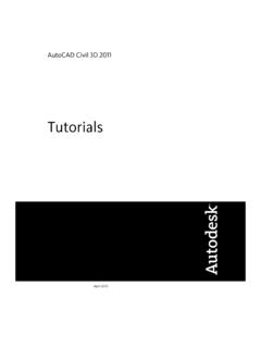
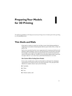
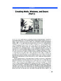
6 With these new tools, surfaces can now be created and manipulated, or they can be thickened to create solid masses. Both surfaces and the solid faces also now serve as the basis for the new custom panel families. This white paper focuses primarily on the solid Modeling workflow the most appropriate technique for a volumetric Design and demonstrates how these masses can be incorporated into a Revit Architecture project. Maximizing Buildable Volume To visualize the extents of the maximum buildable volume, the full parcel is extruded to the maximum height (150 meters) using the Create Form button, a new context aware geometry creation feature that replaces individual Modeling commands such as Extrusion, Sweep, and Blend. This Conceptual mass family is placed into a Revit Architecture project containing the site and surrounding context. Levels are then used to create mass floors from the maximum buildable volume, and a mass floor schedule is generated showing a total buildable area of 35,205 square meters.
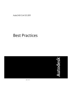
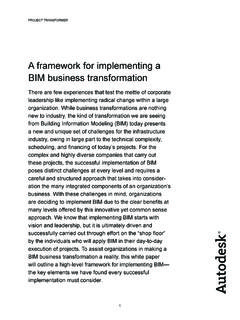
7 Conceptual Mass in the Project Environment Mass Floor Schedule 4 Conceptual Design Modeling IN Autodesk Revit ARCHITECTURE 2010 Although these results might be ideal for the developer, they leave much to be desired from both urban and aesthetic perspectives. In addition, city planning officials would likely have concerns. However, by utilizing the new Conceptual mass tools in Revit Architecture, these issues can be more readily addressed. Responding Intuitively to Urban Context For the tower to respond to its urban context, the programmatic volume requires fundamental modifications to create better public space at the street level. To address this, the north face of the Conceptual mass is split using the Add Profile and Add Edge tools, allowing for a more generous pedestrian walkway and providing better light and air to the adjacent building to the north. 5 Performing this action allows the Design team to manipulate the Conceptual mass in a variety of ways.
8 In this situation, the lower section of the mass is moved away from the adjacent building. As a result of moving the east face of the Conceptual mass, an entrance plaza and public space adjacent to the low-rise residential district can be created. With the quick edits in place, potential city planning concerns have been addressed. Increasing Project Precision In order to understand the impact that Design modifications have on the programmatic requirements, the Conceptual mass is updated in the Revit Architecture project. Accordingly, the mass floors and corresponding area schedule in Revit Architecture are both automatically updated to reflect changes. Conceptual Design Modeling IN Autodesk Revit ARCHITECTURE 2010 With modifications in place, the current Conceptual mass is now 1,990 square meters over the program target. Up until this point, Design modifications have been made graphically via direct manipulation techniques. In order to better control the precision of future modifications, reference planes and parameters are now added, enabling increased degrees of control through numeric input.
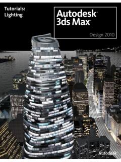
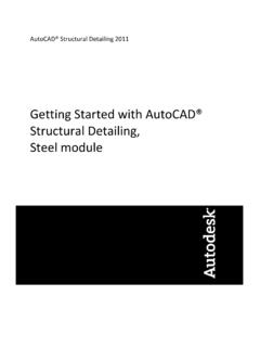
9 With the introduction of bidirectional parameters, the model is modified using both numerical and graphical means. Changes made using the direct manipulation tools will now conversely update the numerical parameters in the model. The introduction of parameters also provides the flexibility to make changes directly from within the project environment, giving the Design team instant feedback from area schedules. 6 The tower Design now satisfies the requirements of both the client and city planners; however, additional steps should still be taken to further refine the building form and environmental impact. Minimizing the Impact of Shadows Reducing the overshadowing of the tower on neighboring buildings and streets becomes the primary concern at this stage of the Design process. By enabling the interactive shadow tools within Revit Architecture, the Design team can quickly identify troublesome areas. To address these areas, the west face of the Conceptual mass is altered to reduce the impact of shadows on the existing towers to the west of the site.
10 With this simple action, the project team reduces the effects of overshadowing, sculpts the top of the tower, and verifies that modifications meet program targets. Conceptual Design Modeling IN Autodesk Revit ARCHITECTURE 2010 Maximizing Solar Collection With the building form beginning to take shape according to programmatic and site requirements, consideration is now given to designing for solar collection. Autodesk Ecotect Analysis 2010 software, an interactive early stage building performance simulation tool, is used for solar insolation analysis. After importing the building form into Ecotect Analysis, tests reveal that the buildings to the west cast shadows across the western face of the tower, while the southern face, particularly near the top, is largely unobstructed. 7 Based on the information provided by Ecotect Analysis, the southern face is further refined in Revit Architecture. Using the Add Edge tool, an edge is added to the south face, creating a top vertex that is then modified via direct manipulation.