Transcription of CONDUCTOR SHORT-CIRCUIT PROTECTION Introduction
1 CONDUCTOR SHORT-CIRCUIT PROTECTION 2000 Cooper Bussmann, Inc. Page 1 of 1012/17/01 Introduction :This paper analyzes the PROTECTION of wire from fault currents. It gives the specifier thenecessary information regarding the SHORT-CIRCUIT current rating of wire. Proper PROTECTION of wire willimprove reliability and reduce the possibility of injury. Wire can be destroyed if the overcurrentdevices do not limit the SHORT-CIRCUIT current to within the SHORT-CIRCUIT current rating of the matching the ampere rating of the wire with the ampere rating of a protective device will notassure component PROTECTION of the wire under SHORT-CIRCUIT the past several years, there have been numerous reports in newspapers, magazines andinsurance company files about destroyed electrical systems.
2 Recognizing this as a serious problem tosafety of life and property, much more emphasis has been placed on COMPLIANCE with THE 2002 NATIONAL ELECTRICAL CODE (NEC) .The NEC covers COMPONENT PROTECTION in several sections. The first section to note isSection PROTECTION and the NEC:Per NEC circuit Impedance and Other Characteristics:"The overcurrent protective devices, the total impedance, the component SHORT-CIRCUIT currentratings, and other characteristics of the circuit to be protected shall be selected and coordinated aspermit the circuit -protective devices used to clear a fault to do so without extensive damage to theelectrical components of the circuit . This fault shall be assumed to be either between two or more of thecircuit conductors, or between any circuit CONDUCTOR and the grounding CONDUCTOR or enclosing metalraceway.
3 Listed products applied in accordance with their listing shall be considered to meet therequirements of this section."This requires that overcurrent protective devices, such as fuses and circuit breakers be selectedin such a manner that the SHORT-CIRCUIT current ratings of the system components will not be exceededshould a SHORT-CIRCUIT SHORT-CIRCUIT current rating is the maximum SHORT-CIRCUIT current that a component canwithstand. Failure to provide adequate PROTECTION may result in component destruction under SHORT-CIRCUIT first step to verifying CONDUCTOR SHORT-CIRCUIT PROTECTION is to calculate the short -circuitcurrent fault levels throughout the electrical system. The next step is to check the SHORT-CIRCUIT currentrating of wire and cable, based upon the calculated SHORT-CIRCUIT fault current available and theovercurrent protective device : The let-through of the protective device must be equal to or less than the SHORT-CIRCUIT currentrating of the component being : Choosing overcurrent protective devices strictly on the basis of voltage, current, andinterrupting rating alone will not assure component PROTECTION from SHORT-CIRCUIT currents.
4 Highinterrupting capacity electromechanical overcurrent protective devices, especially those that are notcurrent-limiting, may not be capable of protecting wire, cable or other components within high SHORT-CIRCUIT ranges. The interrupting rating of a protective device pertains only to that device and hasabsolutely no bearing on its ability to protect connected down-stream components. Quite often, animproperly protected component is completely destroyed under SHORT-CIRCUIT conditions while theprotective device is opening the faulted circuit without damage to itself. 2000 Cooper Bussmann, Inc. Page 2 of 1012/17/01 CONDUCTOR SIZE: SHORT-CIRCUIT Currents for InsulatedCablesThe recent increase in KVAcapacity of power distribution systems hasresulted in possible SHORT-CIRCUIT currents ofextremely high magnitude.
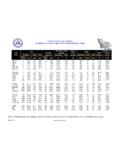
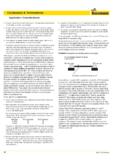
5 Fault induced,high CONDUCTOR temperatures may seriouslydamage CONDUCTOR a guide in preventing suchserious damage, maximum allowable SHORT-CIRCUIT temperatures, which begin to damagethe insulation, have been established forvarious insulation such as, Thermoplastic at150 Insulated Cable EngineersAssociation (ICEA) PROTECTION chart, to theright, shows the currents, which, afterflowing for the times indicated, willproduce these maximum temperatures foreach CONDUCTOR size. The system SHORT-CIRCUIT capacity, the CONDUCTOR cross-sectional area and the overcurrent protectivedevice opening time should be such thatthese maximum allowable short -circuitcurrents are not the formula shown on theICEA PROTECTION chart will allow theengineer to calculate SHORT-CIRCUIT currentratings of cable not shown on these pages.
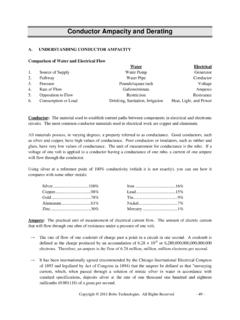
6 Itmay be advantageous to calculate SHORT-CIRCUIT current ratings below one cycle, when the opening time of the current-limiting deviceis Equipment Grounding Conductors:Safety issues arise when the analysis of equipment grounding conductors is discussed. of the NEC offers minimum sizing for equipment grounding problem of protecting equipment grounding conductors was recognized more than 30 yearsago when Eustace Soares, wrote his famous grounding book Grounding Electrical DistributionSystems for Safety . In his book he states that the validity rating corresponds to the amount of energyrequired to cause the copper to become loose under a lug after the CONDUCTOR has had a chance to coolback down. This validity rating is based upon raising the copper temperature from 75 C to 250 addition to this and the ICEA charts, a third method promoted by Onderdonk allows thecalculation of the energy necessary to cause the CONDUCTOR to melt (if the copper CONDUCTOR reaches atemperature 1,083 C).
7 Table 1 offers a summary of these values associated with various size copperconductors. 2000 Cooper Bussmann, Inc. Page 3 of 1012/17/01It becomes obvious that the word Minimum in the heading of table means just that -the values in the table are a minimum - they may have to be increased due to the available short -circuitcurrent and the current-limiting, or non-current-limiting ability of the overcurrent protective engineering practice requires the calculation of the available SHORT-CIRCUIT currents (3-phase and phase-to-ground values) wherever equipment grounding conductors are used. Overcurrentprotective device (fuse or circuit breaker) manufacturers literature must be consulted. Let-throughenergies for these devices should be compared with the SHORT-CIRCUIT current rating of the equipmentgrounding conductors.
8 Wherever let-through energies exceed the minimum equipment groundingconductor SHORT-CIRCUIT current ratings, the equipment grounding CONDUCTOR size must be increased untilthe SHORT-CIRCUIT current ratings are not 1: Comparison of 75 C CONDUCTOR 5 Second Current and I2t Ratings (Based on RMS Amperes)5 Second Rating (Amps)I2t Rating (Amperes Squared Seconds)CondSizeCondAreaCirc. MilsICEAI nsulation150 Deg. CSoaresAnnealing250 Deg. COnderdonkMelting1083 Deg. CICEAI nsulation150 Deg. CSoaresAnnealing250 Deg. COnderdonkMelting1083 Deg. C14 14470351004674982669600 1009033389 20837305456731975044700 1373406557 28361887979162966032750 1576614670 3255828976 10518711006800 1793837136 3704409857 11967955634900 2270325125 4688393726 151469438491000 2802870525 5788140402 18699930677 2000 Cooper Bussmann, Inc.
9 Page 4 of 1012/17/01 Table 1 illustrates the CONDUCTOR rating for 5 seconds as well as the maximum I2t rating basedupon equipment grounding CONDUCTOR size and the CONDUCTOR damage level selected (ICEA, Soares orOnderdonk). However, depending upon the device selected and the resulting opening time, the amountof current the equipment grounding (or phase) CONDUCTOR can handle will need to be adjusted. This isillustrated in the following tables and is valid for both phase and equipment grounding 2 shows the maximum SHORT-CIRCUIT current rating of the CONDUCTOR based upon theopening time of the device. This table is based upon the ICEA Insulation damage level to raise theconductor from 75 degrees C to 150 degrees C. The opening time of the device can depend upon thedevice selected or the short time setting of the device.
10 For example a low voltage power circuit breakercan have a short time delay of up to 30 cycles. Molded case circuit breakers can have similar short timedelay settings up to the instantaneous setting or the instantaneous 2: Maximum SHORT-CIRCUIT Current Rating In Amperes (Per ICEA 75 C Insulation Damage)Maximum SHORT-CIRCUIT Current Rating In RMS AmperesCondCond1/2* Seconds Seconds Seconds Seconds Seconds Seconds Seconds Seconds14 AWG411023841685119297368848739734430812 AWG6530378726781894154610937736315474891 0 AWG1038060204257301024581738122910038697 778 AWG1651095756771478839092764195415961382 12366 AWG2624015218107617609621343933106253621 9719654 AWG4174024207171171210498836988494140353 49431253 AWG5262030517215791525912459881062295086 440539402 AWG6636038486272131924315712111107856641 4555549681 AWG8369048536343202426819815140119907808 9700662661/0 AWG1056006124343305306212500217679125011 0207884079062/0 AWG1331007719254583385963151322283157571 28651114299653/0 AWG1678009731668813486583972928093198651 621914046125634/0 AWG2116001227188677561359500993542625050 204531771315843250