Transcription of Considerations for Measuring Loop Gain in Power Supplies
1 Power Supply Design Seminar Considerations for Measuring Loop Gain in Power Supplies Reproduced from 2018 Texas Instruments Power Supply Design Seminar SEM2300, Topic 6. TI Literature Number: SLUP386. 2018 Texas Instruments Incorporated Power Supply Design Seminar resources are available at: Considerations for Measuring Loop Gain in Power Supplies Manjing Xie Abstract Loop gain measurements show how stable a Power supply is and provide insight to improve output transient response. This presentation discusses the theory of open -loop transfer functions and empirical loop gain measurement methods. The presentation then demonstrates how to configure the frequency analyzer and prepare the Power supply under test for accurate loop gain measurements.
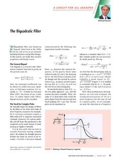
2 Examples are provided to illustrate proper loop gain measurement techniques. I. Introduction Figure 2 includes a Power stage, the output feedback resistor divider, pulse width modulation Loop gain is the product of all gains around a (PWM) comparator and error amplifier with feedback loop. Figure 1 shows a simple system compensation network. The Power stage contains with negative feedback. the Power devices, magnetics and capacitors, which VOUT. VIN +. G(s) transfer energy from the input source to the output. - The output is sensed by the feedback resistor divider. T(s). The error amplifier with the compensation network forms the compensator which amplifies the error between the output feedback (FB) and the reference H(s) voltage, VREF.
3 The output of the compensator, COMP, is modulated by the PWM comparator Figure 1 Block diagram of a feedback system. which converts COMP, a continuous signal, into a discrete driving signal. When the driving signal is The loop gain of this system is defined as: high, the buck converter low-side MOSFET is T (s)=G(s) H(s) (1) turned off and high-side MOSFET is turned on. When the driving signal is low, the buck converter A. Feedback Loop of a Power Supply high-side MOSFET is turned off and low-side A Power supply is usually a more complicated MOSFET is turned on. For a voltage mode buck system than what is shown in Figure 1. Figure 2 converter, the modulation gain is one divided by the Topic 6.
4 Shows a typical buck converter with voltage mode amplitude of the ramp signal. The amplitude of the control. ramp signal is in reverse proportion to VIN to VIN. Power VOUT maintain a constant DC gain over the input range. Stage L VOUT. This technique is called input feed forward. COUT The loop gain, T(s), of the buck converter PWM. Comparator control system is the product of all the gains: - T(s) RTOP. T ( s ) = GPS ( s ) GCOMP ( s ) Fm (2). +. - FB GPS (s) is the Power stage gain from the duty-cycle COMP + VREF to the output. GCOMP (s) represents the transfer Error Amplifier RBOTTOM. function of the error amplifier, compensation network and resistor divider.
5 Fm is the PWM. Figure 2 A voltage mode buck modulation gain. converter control system. 6-1. B. Loop Gain Relation to System Stability brink of instability. In addition, this converter is Loop gain, T, varies with frequency and can be also considered conditionally stable since the phase expressed in the form of a Bode plot. Figure 3 is less than 0 when the gain is greater than 1. The shows the loop gain measured in Bode plot format Bode plot gives the Power supply designer for a buck converter. information regarding the stability that can be used to adjust the compensation network accordingly. Figure 3 Bode plot for loop gain of a buck converter. IOUT VOUT (AC).
6 A Bode plot is a combination of a magnitude plot and a phase plot, both as a function of Figure 4 Output load transient response of a frequency. The blue plot in Figure 3 is the buck converter with 15 phase margin. magnitude plot in dBs and the red plot is the phase shift in degrees. The phase margin (PM) is the C. Loop Gain Bandwidth Relationship to difference between the phase and 0 at zero dB. Output Transient Response gain. When phase margin is zero or negative, the When the system is stable, the output transient system is unstable. response is closely related to the bandwidth of the Gain margin (GM) is another measure of loop loop gain, as discussed in [1] and [2].
7 The loop gain that indicates the stability of the system. Gain gain bandwidth, fC, the frequency at which the margin is the amount of gain increase required to magnitude of the loop gain equals one. Output make the loop gain unity at the frequency where transient overshoot and undershoot is inversely the phase shift is -180 . In other words, the gain proportional to the loop gain bandwidth. Figure 5. margin is 1/G if G is the gain at -180 phase shift shows a typical output load transient response. frequency. In Figure 3, the phase shift measurement Topic 6. includes an additional phase-shift of 180 due to negative feedback. While a system is theoretically considered stable with even 1 phase margin, component variation or load/line variation can affect the frequency response and make the system unstable.
8 The phase margin requirement is usually from 45 to 60 . The phase margin of this converter is only 15 at 22 kHz and the stability is considered marginal. Figure 4 shows the corresponding output load transient response. The purple trace is the load current waveform. The blue trace is the AC-coupled output voltage. The output voltage ringing after the load transient indicates that the system is on the Figure 5 Output load transient response of a buck converter [1]. 6-2. The overshoot or undershoot, VP, can be Middlebrook proposed Measuring loop gain in a estimated with: closed-loop setup in [3]. With the feedback loop I closed, a small test voltage source or test current VP = (3) source is injected into the loop.
9 By Measuring the 2 fC COUT. resulting response of the two points across the test where: voltage source or current source into the two ITRAN is the transient load current step, points, the loop gain can be derived. Since the fC is the loop gain control bandwidth and voltage injection method is the most practical and COUT is the Power supply output capacitance. widely adopted method, this paper focuses on the The delay time from the start of the current voltage injection method. VIN. transient to the output transient peak or valley, tP, Power VOUT. can be approximated by: Stage L VOUT. B. 1 COUT ~. VINJ. tP = (4) PWM. 4 fC Comparator A. Thus, the loop gain measurement assists the - T(s) RTOP.
10 +. Power supply designer in tuning the compensation network to improve the output transient response performance. - FB. COMP + VREF. Given the importance of the loop gain, it is Error Amplifier RBOTTOM. necessary to ensure loop gain measurement accuracy. This paper focuses on the methods and Considerations for Measuring loop gain Figure 6 Measuring loop gain of a Power experimentally. The goal is to provide guidelines supply in open -loop setup. for accurate loop gain measurement on which Power supply designers can rely for compensation When the feedback loop is broken at any network design. point, such as that shown in Figure 6, looking backward, looking into point B, and applying Thevenin's theory, the circuit is equivalent to a II.