Transcription of Controller Area Network Physical Layer Requirements
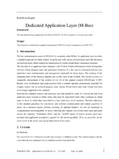
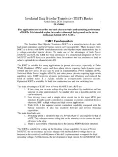
1 ApplicationReportSLLA270 (CAN),ISO11898:1993,isfindingwidespreadu seinbuildingautomation,processcontrol, , (bittimingrequirements).. ( ).. LayerData-LinkLayerLogic Link ControlMedium Access ControlPhysicalLayerPhysical SignalingPhysical Medium AttachmentMedium Dependant InterfaceEmbeddedCANC ontrollerCANT ransceiverCAN BusLine Electricalspecifications:transceivers,co nnectors, cable CANcontroller,embedded shighreliability, ,hardwareinterfacecards, :1993 StandardArchitectureFigure1displaystheIS O11898standardarchitectureusingthebottom twolayersoftheOSImodel, ,andaftersendingamessage, , sand0 sintoelectricalpulsesleavinganode, , , 1 CANNODE 2 CANNODE 3 RECEIVE-ONLYNODE Bytes DataCCRRCCACKEOFEOFEOFFISIIDDEErr00 DDLLCC11- bitI dentifierRTRSOF11- bitI dentifi erRTRIDEr 0D L C0 ..8C R CA C Kr 118-bitI dentifierSRRSOFB ytes , ,onlythosenodesrequiringupdateddataallow themessagetopassthroughafilterthatissetb ythenetworkdesigner ,messagesfromcertainnodescanpass, ,muchofanode's ,thatasystemdesignercanusetoidentifythec ontentofamessage.
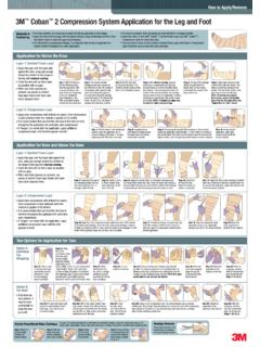
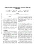
2 29-BitIdentifierCAN' , , C wins arbitrationACK bitACK bitACK bitNODEANODEBNODECCANBus4 PhysicalLayerRequirementsPhysicalLayerRe quirementsAllnodesonabusparticipateineac hbit , , ,NodesBandCthenbeginarbitration ' , , ,whicharenormallytransparenttoasystemope rator,areincludedinanycontrollerthatimpl ementstheCANprotocolsuchastheTexasInstru mentsTMS320F2812 (thebus)isthenimplementedthroughalinetra nsceiversuchasTI Bus-LineRLCANC ontroller(Node #1)DSP or C CANT ransceiverCANC ontroller(Node #n)DSP or C CANT ransceiverCANC ontroller(Node #2)DSP or C CANT ransceiverCANC ontroller(Node #3)DSP or C characteristicimpedance(ZO). resistors, , (m)(Mbps) ,themaximumbuslengthisdeterminedby, , ,whichdegradethesignaltransitiontimeandi ntroduceinter-symbolinterference(ISI), ,thesignalingrateisalsodeterminedfromthe totalsystemdelay downandbackbetweenthetwomostdistantnodes ofasystemandthesumofthedelaysintoandouto fthenodesonabuswiththetypical5 , ,skineffects,proximitytoothercircuitry,d ielectricloss, , (Mbps) BusLength(m) 50 SLLA270 , , srecommended30nodesmayrequiretheuseofhig hercablequality,aCANbusrepeater,andtight eroperatingtolerancessuchasa5% ,however,almostanytypeofcableworkstoacer taindegree, cableisusedinmanyapplications, , s 2 Vto7 Vcommon-moderangeoftolerablegroundoff-se t, ,theyaremoreeasilyinstalledandverified,a ndmay,therefore, , , , , (SLLS629)
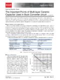
3 , RLoneachendofthebus,orthesplitterminatio nusingtwo60 , ,abus-lineshort-circuittoa24 Vsupplylinewouldgenerateatransceiver SingleorSplitTerminationSLLA270 - pass filter withp2 RCL1fc=60W60W60 Wnode 1node nnode bus pin3V+Optional or 5-V power supply fortransceivers and digital isolators if required4 Reserved5 CAN_SHLD Optional shield6V-Ground return path/ 0V7 CANHCANH bus pin8 Reserved9V+Optional or 5-V power supply fortransceivers and digital isolators if requiredPhysicalLayerRequirementsNotetha ttransceiverssuchastheSN65 HVD1050haveaVreforVsplitpinshowninFigure 9thatisspecificallydesignedtostabilizeth ecommon-modebusvoltageduringcommunicatio n(thisalsohelpsreduceradiatedemissions). TheHVD1050 ~60 1% , , ,whilenotspecifiedbytheStandard,shouldha veacharacteristicimpedancematchingthatof thebuslineandterminators, , ,Multipole,RJ10,RJ45,M12,the5-pinmini-st yleinFigure12andmoremicro-styleconnector sintheCiAspecificationdocumentDR303-1, Optional shield2V+Optional or 5-V power supplyfor transceivers and digital isolatorsif required3V-Ground return path/ 0V4 CANHCANH bus pin5 CANLCANL bus ( )Bus-linesandagroundplanecanformaloopfor inductivelycouplednoisesignalsanddependi nguponthetopology, , (T) ,signalreflectionscandevelopinastubthatd rivesignallevelsbackandforthacrossarecei ver'sinputthresholds, , ,stub-linelengthshouldnotexceedone-third (1/3)oftheline' , (tprop(total))ofasignalthroughalineequal sthetransitiontime(tt)ofasignal(thegreat eroftheriseorfalltimes).
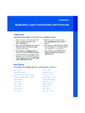
4 NetworkCriticalLength=tt=tprop(total)The refore,atypicalCANdrivermayhavea50nstran sitiontime,andwhenconsideringatypicaltwi sted-pairtransmissionlinepropdelayof5ns/ m,thedown-and-backdelayforonemeterbecome s10 (50ns/10ns/m=5m),andthemaxun-terminateds tublengthforthenetworkis1/3rdofthecritic allength,or5/3m( ).SLLA270 # 1 Node # 2 Node # 3 Node # nMost Distant Nodesdown & backdownbackTransceiversIsolatorsControl lersmt= t+ t+ ttt#n tBUDGETISOLATORTRANSCEIVERBUS_PROPTRANSC EIVERISOLATORCONTROLLER+++t+ t+ tttISOLATORTRANSCEIVERBUS_PROPTRANSCEIVE RISOLATOR++PhysicalLayerRequirementsWhen criticallengthistakenintoconsideration, ,butwithslewratecontrol,reducedsignaling rate,andcarefuldesign, ,ifa10k resistorisappliedforslope-controlattheRs pin(pin8)oftheHVD230 CANtransceiver,a160nsdrivertransitiontim eincreasesthemaximumstublengthto16/3mor5 1 , ,galvanicisolators, :CANcontroller(50nsto75ns),digitalisolat or(17nsforaTIisolatorandupto140nsforanop tocoupler),transceiver(100nsto250ns),and cable(about5ns/m).
5 , :atransmittedbitfromFigure14'sNode#1's C isolatordelay,driverdelay,10mbusdelay,re ceiverdelay,isolatordelay,controllerdela y,isolatordelay,driverdelay,busdelay,rec eiverdelay,isolatordelay receiveitbackto#1's ,17nsfortheTIisolator,100nsfortransceive rsdriverand100nsforthetransceiver sreceiver, ,inFigure14,thetotalpropdelayis:1sttrans mitbitfrom C isolatordelay(17ns),driverdelay(100ns),b usdelay[10m(5ns/m)],receiverdelay(100ns) ,isolatordelay(17ns),controllerdelay(50n s),isolatordelay(17ns),driverdelay(100ns ),busdelay[10m(5ns/m)],receiverdelay(100 ns),isolatordelay(17ns)= ,allowancesforoscillatorvariations,opera tingvariables,etcmustbeaccountedforbefor easignalingrateisselected, (bittimingrequirements)Hardsynchronizati onforces rising edgein first segmentCompensates forpropagationdelaysSample PointSEG 1 may be lengthenedor SEG 2 may be shortenedfor resynchronizationNominal Bit Length( Unit Interval )
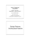
6 SYNC _SEGPROP _SEGPHASE _SEG 1 PHASE _SEG =C,whereListheinductanceperunitlengthand CistheVS120Wt = 0S 1 LoadLoadLoadLoadd120WZ = 120 OWPhysicalLayerRequirementsEachCANbitisd ividedintothefoursegmentsinFigure15,with asamplepointtypicallylocatedatthe75% ,thesynchronizationsegment(SYNC_SEG), ,thepropagationtimesegment(PROP_SEG), ,bothphasebuffersegments(PHASE_SEG1andPH ASE_SEG2), (1) ,connectors,terminators, , ,intheformofdevicesandtheirinterconnecti on,thebusimpedanceisloweredtoZ'andwhenth ebusimpedanceislowered, (1)Capacitancehereisdefinedasdifferentia l, L VJ1where,ZZZZL+ - = > 3 + (-3) + (-3) > = (1)0L00000Z - Z => + ZZ - Z > (Z + Z )Z (1 + ) > Z ( )Z > Z (2)LZ =(C+C ) whereC ,C, ,Lcanbesolvedfromtherelationship0LZ =CasL=200Z CCZ == Z(C+C )C+C' (3) ,theCANdriverdifferentialoutputvoltage,V S, , (2)media, , ,anattenuation(oramplification) +VJ1+VR1,whereVL0istheinitialdominantdif ferentialvoltage,VJ1istheinputsignalrece ssivedifferentialvoltage, +VJ1+ L ,aCANdrivercreatesahigh-to-lowdifferenti alvoltagechangefromthestandardmaximumVLO of3 Vto0V,oraVJ1of ,VL1, ,Now,solvingforZ , ,theadditionofdevices, ,theloaded-busimpedancecanbeapproximated bycapacitanceofthemediawereknown,Z , , andsimplifying,C isthedistributeddevicecapacitance,CL,div idedbythedistance,d,betweendevicesorC = ,(2)Electricallylongisdefinedhereas >(t10% 90%)/3,where istheone-waytimedelayacrossthebusand(t10 % 90%),isthe10%to90% ( )( )( )0L20L2L0L20CZ = ZCC+dCZ'=ZCC +dCZC= C +Z'dCd =ZC-1Z' (4)L200 LCd >ZC-1meters (if C is pF/m) or feet (if C is pF/ft).
7 > (5)Minimum Distance between CAN Distributed Capacitance - pF/mC = 40 pFLC = 30 pFLC = 50 pFLC = 20 pFLC = 10 pFLDistance - mPhysicalLayerRequirementsNowsubstitutin gourminimumZ , ,CL,includescontributionsfromtheCANbuspi ns,connectorcontacts,printed-circuitboar dtraces,protectiondevices, ,suchastheSN65 HVD251, ,suchastheSN65 HVD230, ,suchasRS-485,RS-422,orM-LVDS, ,upto64nodesmaybeconnectedtoaDeviceNetbu s, ,itisrecommendedthatatransceiverwithahig hbus-inputimpedance, ,ithastosinkorsourcealloftheleakagecurre ntonthebus, , , , , 's1 Mbps, January2008 SubmitDocumentationFeedbackIMPORTANT NOTICET exas Instruments Incorporated and its subsidiaries (TI) reserve the right to make corrections, modifications, enhancements, improvements,and other changes to its products and services at any time and to discontinue any product or service without notice.
8 Customers shouldobtain the latest relevant information before placing orders and should verify that such information is current and complete. All products aresold subject to TI s terms and conditions of sale supplied at the time of order warrants performance of its hardware products to the specifications applicable at the time of sale in accordance with TI s standardwarranty. Testing and other quality control techniques are used to the extent TI deems necessary to support this warranty. Except wheremandated by government Requirements , testing of all parameters of each product is not necessarily assumes no liability for applications assistance or customer product design. Customers are responsible for their products andapplications using TI components. To minimize the risks associated with customer products and applications , customers should provideadequate design and operating does not warrant or represent that any license, either express or implied, is granted under any TI patent right, copyright, mask work right,or other TI intellectual property right relating to any combination, machine, or process in which TI products or services are used.
9 Informationpublished by TI regarding third-party products or services does not constitute a license from TI to use such products or services or awarranty or endorsement thereof. Use of such information may require a license from a third party under the patents or other intellectualproperty of the third party, or a license from TI under the patents or other intellectual property of of TI information in TI data books or data sheets is permissible only if reproduction is without alteration and is accompaniedby all associated warranties, conditions, limitations, and notices. Reproduction of this information with alteration is an unfair and deceptivebusiness practice. TI is not responsible or liable for such altered documentation. Information of third parties may be subject to of TI products or services with statements different from or beyond the parameters stated by TI for that product or service voids allexpress and any implied warranties for the associated TI product or service and is an unfair and deceptive business practice.
10 TI is notresponsible or liable for any such products are not authorized for use in safety-critical applications (such as life support) where a failure of the TI product would reasonablybe expected to cause severe personal injury or death, unless officers of the parties have executed an agreement specifically governingsuch use. Buyers represent that they have all necessary expertise in the safety and regulatory ramifications of their applications , andacknowledge and agree that they are solely responsible for all legal, regulatory and safety-related Requirements concerning their productsand any use of TI products in such safety-critical applications , notwithstanding any applications -related information or support that may beprovided by TI. Further, Buyers must fully indemnify TI and its representatives against any damages arising out of the use of TI products insuch safety-critical products are neither designed nor intended for use in military/aerospace applications or environments unless the TI products arespecifically designated by TI as military-grade or "enhanced plastic.