Transcription of Coupled Inductors
1 Coupled InductorsFrom power distribution across large distances to radio transmissions, Coupled Inductors are used extensively in electrical applications. Their properties allow for increasing or decreasing voltage and current, transferring impedance through a circuit, and they can isolate two circuits from each other electrically. There are a wide variety of applications which exploit properties of transformers, such as tesla coils, impedance matching in audio frequency applications, potential transformers for reading very high voltages, Scott-T transformers which convert two-phase components to three-phase (or vice versa), and many module explains the functions of Coupled Inductors and explores the equations governing their performance.
2 It will present mutual inductance, dot notation, the coupling coefficient, the turns ratio, and finally the ideal transformer. This module will explain how to model Coupled Inductors and provide modeling examples in MapleSim. Introducing Coupled InductorsAs current flows through a conductor, a magnetic field is generated. Steady-state current will induce a steady magnetic field, and likewise a time-varying current will induce a time-varying magnetic field. Nearby conductors will generate a current as the varying magnetic flux permates the conductor, as stated by Faraday's law. This principle is known asinductance. To begin investigating Coupled inductance, recall that the voltage across an inductor is proportional to the change in Eq.
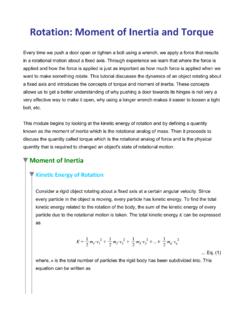
3 (1)L is the inductance of the conductor, in henry's. Figure 1: Two coils are magnetically Coupled , wound around a magnetic core . With Coupled Inductors , such as those shown in figure 1, two wires are wrapped around a magnetic core . In this diagram, note that the two wires are wrapped around the core in opposite directions and produce the same polarity of voltage. This is due to Lenz's law. A varying magnetic field, generated by the current , will induce a current in the opposite direction on the Coupled coil. Heinrich Lenz added the negative sign to Faraday's law of induction, below.. Eq. (2)Here, is the change in magnetic flux and is the electromotive force. The flux within the magnetic core of the Coupled Inductors depends on the material of the core , the number of turns of the wire around the core , and the current.
4 Eq. (3)The voltage across the inductor is related to the flux by the number of turns of the Eq. (4)This shows that we can draw a connection between eq. (1) and eq. (4).. Eq. (5)The voltage across the second inductor follows eq. (4). The magnetic flux will be the same (as induced by the first coil), and we derive and equation for the mutual inductance.. Eq. (6) The variable M is the mutual inductance of the system, in henrys. This depends on the geometrical properties of the coils, such as the number of turns and radii of the turns of each coil.. Eq. (7)A dot convention is used to specify the direction of the windings around the core . Dots on the same ends of the inductor, like in figure 1, mean that the coils are wrapped clockwise-counterclockwise to each other.
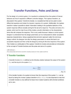
5 If the dots are on the opposite sides like figure 2 shows, then the coils are wrapped in the same directions (clockwise-clockwise or counterclockwise-counterclockwise). Figure 2: Coupled inductor with dot notationIt's important to note that the dot convention follows passive convention. Although figure 2 displays the voltages as the same polarity, one of the voltages will be negative. The dot convention states:If the current enters the dotted terminal of one coil, the voltage will be positive at the dot on the second , the voltage of the second coil will be negative if the current leaves the dotted terminal of the first coil. Figure 3 illustrates the passive convention. Figure 3: Induced voltage of Coupled voltage is the voltage induced by the Coupled current.
6 A transformer can have current entering from both the first and second coils. The voltage across each coil will be dependanton the current through this coil and the induced voltage from the other coil. Suppose the dots are on the same end, and both currents enter at the dots. The voltages will be, and .. Eq. (8)If the dots are on the opposite sides of each other, then the voltages will be, and .. Eq. (9)Because the induction relies on a changing current, Coupled Inductors must be used with alternating current. This means that we can analyse Coupled Inductors in the frequency domain as phasors. Eq. (8) and eq. (9) can be represented with phasors as eq. (10) and eq.
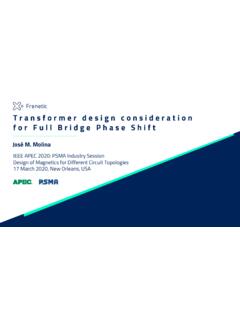
7 (11), respectively. and .. Eq. (10) and .. Eq. (11)The Coupling CoefficientThe coils and mutual inductances depend on material properties of the core . The factorc used represents these properties in a lumped product. Explicity, c is the product of the permeability of free space and the core , the cross-sectional area, and the inverse of the length of the coils.. Eq. (12)From eq. (5) and eq. (7), the mutual inductance is related to the coils inductances Eq. (13)However, this assumes a perfect flux linkage between the two conductors. Figure 4: Flux lines cutting through the flux lines will not cut through the Coupled inductor, which will affect the mutual inductance.
8 Therefore, eq. (13) is multiplied by the coupling coefficient k, a value between 1 (perfectly linked Inductors ) and 0 (uncoupled Inductors ). Eq. (13) Eq. (14)A coupling coefficient of can imply that 75% of the flux lines cut through the other inductor. Different applications try to achieve different coupling coefficients, for example radio circuits will result in low k values and many power system transformers aim for k = TransformersTurns Ratio and Step TransformersThe primary coil in a transformer is the coil connected to the source voltage. Thesecondary coil is attached to the load of the circuit. The turns ratio is the ratio of some value of the second coil to the first. The turns ratio is defined Eq.
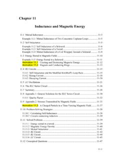
9 (15)Where V is the voltage of the transformers at each coil, I is the current, N is the number of turns of each coil, and L is the inductance of the coils. The turns ratio determines whether a transformer will step-up or step-down. A transformer that steps-up the voltage, that is the secondary voltage is greater than the primary voltage, will also step-down the current. Conversely, stepping down the voltage will increase the current on the secondary ) b) Figure 5: a) Step-up transformer, b) Step-down transformerThe voltage of the secondary inductor can then be found with this ratio, and it is related to the primary Eq. (16)One big advantage to AC electricity is that it can travel across large distances more efficiently than DC electricity.
10 Power companies use transformers to step-up the voltage as electricity leaves the power plant. Once it arrives at the customer's house, a step-down transformer reduces the voltage down to 110 V or 220 V and increases the current. In theseapplication, it is ideal that the coupling coefficient be as high as possible to reduce lost energy. The ideal transformer is a transformer which has a coupling coefficient equal to 1 (unity). The important factor in an ideal transformer is the turns ratio, which determines the magnitude of the step. They are used to raise and lower voltage and for isolating circuits from each other. Figure 6: An ideal transformerAn ideal transformer does not absorb or store any electrical power while in operation.