Transcription of Oscillators - Learn About Electronics
1 AMPLIFIERS 1 E. COATES 2007 -2013 Oscillators RF Sine Wave Oscillators RF Oscillators Radio Frequency Oscillators There are many different designs of sine wave Oscillators used in radio and communication equipment, usually using some form of resonant circuit to generate signals at radio frequencies from several tens of kHz to 1 GHz and above. A number of popular oscillator designs date back to the early 20th century when radio communication was being developed, and it has been the custom to name the various types of oscillator after their inventor. Any one particular design of oscillator can have several different forms, and each type of oscillator has certain advantages and disadvantages for any particular application.
2 This module describes some popular types of LC and crystal sine wave Oscillators , how they work and includes some practical projects showing how to build and test some RF Oscillators . Module 2 What you ll Learn in Module 2 Section High Frequency Sine Wave Oscillators . Frequency Control in RF Oscillators . LC Networks. Quartz Crystals. Ceramic Resonators. Section The Hartley Oscillator. The Tuned Tank Circuit. Automatic (Sliding) Class C Bias. How the Hartley Oscillator Works. Alternative Hartley Designs. Section Hartley Oscillator Practical Project. Building a Hartley Oscillator. Hartley Oscillator Tests & Measurements. Section The Colpitts Oscillator. Using a Common Base Amplifier. Using a Common Emitter Amplifier.
3 Output Buffering. Section Colpitts Oscillator Practical Project. Building a Colpitts Oscillator. Colpitts Oscillator Tests & Measurements. Section Crystal Oscillators . Frequency control in LC Oscillators . Quartz Crystal Oscillators . Section LC Oscillator Quiz Test your knowledge of LC Oscillators . Oscillators Module 2 Oscillators MODULE 2 E. COATES 2007-2013 Frequency Control in RF Oscillators Several different types of frequency control networks are used in high frequency sine wave Oscillators . Three of the most commonly found are: 1. LC Network, 2.
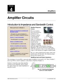
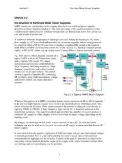
4 Quartz Crystal, 3. Ceramic Resonator. LC Networks In networks, consisting of an inductors and capacitors the frequency of oscillation is inversely related to the values of L and C. (the higher the frequency, the smaller the values of L and C). LC Oscillators generate a very good shape of sine wave and have quite good frequency stability. That is, the frequency does not change very much for changes in supply voltage or in ambient temperature. LC Oscillators are extensively used for generating signals where good wave shape and reasonable frequency stability is required but is NOT of prime importance. Quartz Crystals Crystal Oscillators are used to generate both square and sine waves at frequencies around 1 or 2 MHz and higher, when a very high degree of frequency stability is needed.
5 The component determining the frequency of oscillation is thin slice of crystalline quartz (Silicon Dioxide), usually sealed inside a metal can. The quartz crystal vibrates mechanically at a very precise frequency when subjected to an alternating voltage. The frequency depends on the physical dimensions of the slice and the angle at which the slice is cut in relation to the atomic structure of the crystal, and so once the crystal has been manufactured to specific dimensions, its frequency is extremely accurate, and constant. The frequency produced is typically accurate to around of its design frequency and is almost wholly independent of changes in supply voltage and variations in temperature over its working range. Where even greater accuracy is required, the crystal may be mounted in a small, heated and temperature controlled enclosure.
6 Crystals are manufactured in a wide range of specific frequencies. Sine wave crystal Oscillators are commonly used to generate very accurate frequency carrier waves in radio and other communications transmitters. Ceramic Resonators These components work in a similar way to quartz crystals, they vibrate when subjected to an AC signal, but are manufactured from a variety of ceramic materials. Thay are generally cheaper and physically smaller than equivalent quartz crystal resonators, but do not have such a high degreee of accuracy. They can be manufactured in either surface mount or through hole versions having either two or three connections. Oscillators Module 2 Oscillators MODULE 3 E.
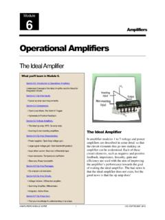
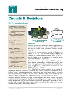
7 COATES 2007-2013 What you ll Learn in Module After Studying this section, you should be able to: Understand the operation of The Tuned Tank Circuit. Understand the operation of Automatic (Sliding) Class C Bias. Understand the operation of Hartley Oscillators . Recognise Alternative Hartley Designs. The Hartley Oscillator The Hartley Oscillator is a particularly useful circuit for producing good quality sine wave signals in the RF range, (30kHz to 30 MHz) although at the higher limits of this range and above, The Colpitts oscillator is usually preferred. Although both these Oscillators oscillator use an LC tuned (tank) circuit to control the oscillator frequency, The Hartley design can be recognised by its use of a tapped inductor (L1 and L2 in Fig.)
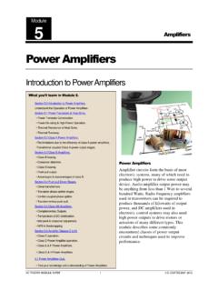
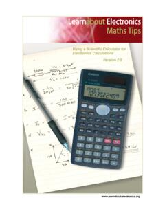
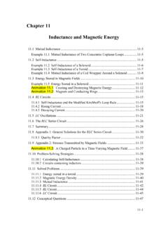
8 The frequency of oscillation can be calculated in the same way as any parallel resonant circuit, using: Where L = L1 + L2 This basic formula is adequate where the mutual inductance between L1 and L2 is negligible but needs to be modified when the mutual inductance between L1 and L2 is considerable. Mutual Inductance in Hartley Oscillators Mutual inductance is an additional effective amount of inductance caused by the magnetic field created around one inductor (or one part of a tapped inductor) inducing a current into the other inductor. When both inductors are wound on a common core , as shown in Fig. the effect of mutual inductance (M) can be considerable and the total inductance is calculated by the formula: LTOT =L1 + L2 2M Fig. The Hartley Oscillator Fig.
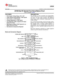
9 Centre Tapped Inductors on a Common core Oscillators Module 2 Oscillators MODULE 4 E. COATES 2007-2013 The actual value of M depends on how effectively the two inductors are magnetically coupled, which among other factors depends on the spacing between the inductors, the number of turns on each inductor, the dimensions of each coil and the material of the common core . With separate fixed inductors, as shown in Fig. considerations of mutual inductance are simplified, the dimensions and number of turns for each inductor are fixed, therefore main considerations are the physical distance between the inductors and the direction of their magnetic fields.
10 In practice the small values of inductance of the inductors needed at RF create very little magnetic field outside the component and only when mounted within a couple of millimetres of each other is the mutual inductance effect noticeable, as shown in Fig. Whether M, measured in Henrys or more likely micro Henrys ( H) in RF Oscillators adds to or subtracts from the total inductance of very closely mounted tapped inductors depends on the North-South polarity of the fields around the individual coils L1 and L2, if the magnetic fields are both in the same direction, the mutual inductance will add to the total inductance but if the magnetic fields are arranged to oppose each other, as in the effect of the mutual inductance will be to reduce the total inductance and so increase the actual working frequency of the oscillator.