Transcription of CP2105 - Silicon Labs
1 Rev. 11/13 Copyright 2013 by Silicon LaboratoriesCP2105CP2105 SINGLE-CHIP USB TO DUAL UART BRIDGES ingle-Chip USB to Dual UART Data Transfer Integrated USB transceiver; no external resistors required Integrated clock; no external crystal required Integrated 296-Byte One-Time Programmable ROM for storing customizable product information On-chip power-on reset circuit On-chip voltage regulator: V outputUSB Peripheral Function Controller USB Specification compliant; full-speed (12 Mbps) USB Suspend states supported via SUSPEND pinsTwo UART Interfaces ( Enhanced and Standard ) Flow control options:- Hardware (CTS / RTS)- Software (X-On / X-Off)- No flow control Configurable I/O ( V to VDD) using VIO pin Configurable I/O (VDD to 5 V) using external pull-up All modem interface signals available (when GPIO is not used)Enhanced UART Interface Features Data formats supported: - Data bits: 5, 6, 7, and 8- Stop bits: 1, , and 2- Parity: odd, even, mark, space, no parity Baud rates: 300 bps to Mbps 320 Byte receive and transmit buffers Two GPIO signals for status and control RS-485 mode with bus transceiver controlStandard UART Interface Features Data format: 8 data bits, 1 Stop bit Parity: Even, Odd, No parity Baud rates.
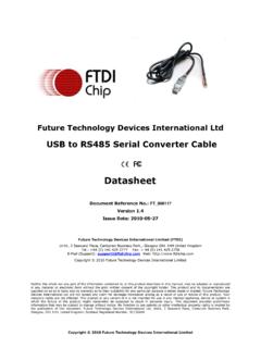
2 2400 bps to 921600 bps 288 Byte receive and transmit buffers Three GPIO signals for status and controlVirtual COM Port Device Drivers Works with Existing COM Port PC Applications Royalty-Free Distribution License Windows 7/Vista/XP/Server 2003/2000 Mac OS-X Linux USBX press Direct Driver Support Royalty-Free Distribution License Windows 7/Vista/XP/Server 2003/2000 Windows CE , , and Voltage Self-powered: to V USB bus powered: to V I/O voltage: V to VDDP ackage RoHS-compliant 24-pin QFN (4 x 4 mm)Ordering Part Number CP2105 -F01-GMTemperature Range: 40 to +85 CFigure 1. Example System DiagramConnect to VBUS or External SupplyVBUSD+D-GNDUSB ConnectorLogic Level Supply( to VDD)Enhanced UART and GPIO SignalsStandard UART and GPIO SignalsCP2105 Data FIFOs48 MHz Oscillator288 B RX288 B TX320 B RX320 B TXEnhanced UART(ECI)Standard UART(SCI)USB InterfacePeripheral Function ControllerFull-Speed 12 Mbps Transceiver296 Byte PROM(Product Customization)Voltage RegulatorGPIO / Handshake ControlGPIO / Handshake Control6 RXD_ECITXD_ECIRXD_SCITXD_SCIRTS_ECICTS_E CIGPIO0_ECI / / DSR_ECISUSPEND / RI_ECINC / DCD_ECI / / / DSR_SCISUSPEND / / DCD_SCIBaud Rate GeneratorECI ClockSCI ClockREGINVDDGNDVIOVBUSD+D-I/O Power and Logic LevelsRSTCP21052 Rev.
3 OF CONTENTSS ectionPage1. System Overview .. 42. Electrical Characteristics .. 53. Pinout and Package Definitions .. 84. QFN-24 Package Specifications .. 115. USB Function Controller and Transceiver .. 136. Asynchronous Serial Data Bus (UART) Interfaces .. ECI Baud Rate Generation .. 147. GPIO Mode and Modem Mode .. 148. GPIO Pins .. Transmit and Receive Toggle .. RS-485 Transceiver Bus Control .. Hardware Flow Control (RTS and CTS) .. 179. One-Time Programmable ROM .. 1810. Voltage Regulator .. 1911. CP2105 Device Drivers .. Virtual COM Port Drivers .. USBX press Drivers .. Driver Customization .. Driver Certification .. 2112. Relevant Application Notes .. 22 Document Change List ..23 Contact Information .. 24CP21054 Rev. System OverviewThe CP2105 is a highly integrated USB-to-Dual-UART Bridge Controller providing a simple solution for updatingRS-232 designs to USB using a minimum of components and PCB space.
4 The CP2105 includes a USB full-speed function controller, USB transceiver, oscillator, one-time programmable ROM, and two asynchronous serialdata buses (UART) with full modem control signals in a compact 4 x 4 mm QFN-24 package (sometimes called MLF or MLP ).The on-chip one-time programmable ROM may be used to customize the USB Vendor ID, Product ID, ProductDescription String, Power Descriptor, Device Release Number, Interface Strings, Device Serial Number, andModem/GPIO configuration as desired for OEM Virtual COM Port (VCP) device drivers provided by Silicon Labs allow a CP2105 -based product toappear as two COM ports in PC applications. The CP2105 UART interfaces implement all RS-232 signalsincluding control and handshaking, so existing system firmware does not need to be modified. The device alsofeatures a total of five GPIO signals that can be user-defined for status and control information.
5 Support forI/O interface voltages down to V is provided via a VIO pin. Direct access driver support is also available throughthe Silicon Labs USBX press driver set. See for the latest application notes and product supportinformation for the evaluation kit for the CP2105 (Part Number: CP2105EK) is available. It includes a CP2105 -based USB-to-UART/RS-232 evaluation board, a complete set of VCP device drivers, USB and RS-232 cables, and fulldocumentation. Contact a Silicon Labs sales representatives or go to to order the CP2105 Evaluation Electrical CharacteristicsTable 1. Absolute Maximum RatingsParameterTest ConditionMinTypMaxUnitAmbient Temperature Under Bias 55 125 CStorage Temperature 65 150 CVoltage on RST, GPIO or UART Pins with respect to GNDVIO > VVIO < V + on VBUS with respect to GNDVDD > VVDD not powered + on VDD or VIO with respect to GND Total Current through VDD, VIO, and GND 500mAMaximum Output Current Sunk by RST or any I/O pin 100mANote:Stresses above those listed may cause permanent damage to the device.
6 This is a stress rating only, and functional operation of the devices at or exceeding the conditions in the operation listings of this specification is not implied. Exposure to maximum rating conditions for extended periods may affect device 2. Global DC Electrical CharacteristicsVDD= to V, 40 to +85 C unless otherwise ConditionMinTypMaxUnitDigital Supply Voltage (VDD) Port I/O Supply Voltage (VIO) VDDVV oltage on VPP with respect to GND during aROM programming operationVIO > VIO + on VPP for ROM programming FSupply Current1 Normal Operation; VREG Enabled Current1 Suspended;VREG Enabled 100220 ASupply Current - USB Pull-up2 200228 ASpecified Operating Temperature Range 40 +85 the device is connected to the USB bus, the USB Pull-up Current should be added to the supply current for total supply The USB Pull-up supply current values are calculated values based on USB 3. UART and Suspend I/O DC Electrical CharacteristicsVDD= to V, VIO= V to VDD, 40 to +85 C unless otherwise ConditionMinTypMaxUnitOutput High Voltage (VOH)IOH= 10 AIOH= 3mAIOH= 10mAVIO VIO VOutput Low Voltage (VOL)IOL=10 AIOL= VInput High Voltage (VIH) x VIO VInput Low Voltage (VIL) Leakage CurrentWeak Pull-Up OffWeak Pull-Up On, VIO=0V 25150 AMaximum Input VoltageOpen drain, logic high (1) 4.
7 Reset Electrical Characteristics 40 to +85 C unless otherwise ConditionMinTypMaxUnitRST Input High x VIO VRST Input Low Voltage RST Low Time to Generate a System Reset15 sVDD Ramp Time for Power On 1msTable 5. Voltage Regulator Electrical Specifications 40 to +85 C unless otherwise ConditionMinTypMaxUnitsInput Voltage VoltageOutput Current = 1 to 100 mA* Detection Input VBias Current 120 A*Note: The maximum regulator supply current is 100 mA. This includes the supply current of the 6. GPIO Output Specifications 40 to +85 C unless otherwise ConditionMinTypMaxUnitRS-485 Active Time After Stop Bit 1 bit time*TX Toggle Rate HzRX Toggle Rate Hz*Note: Bit-time is calculated as 1 / baud Pinout and Package DefinitionsTable 7. CP2105 Pin DefinitionsNamePin #TypeDescriptionVDD6 Power InPower OutPower Supply Voltage Regulator Output. See Section In I/O Supply Voltage Must be tied to I/ODevice Reset.
8 Open-drain output of internal POR or VDD monitor. An external source can initiate a system reset by driving this pin low for the time specified in Table In 5 V Regulator Input. This pin is the input to the on-chip voltage regulator. VBUS8D InVBUS Sense Input. This pin should be connected to the VBUS signal of a USB +3D I/OUSB D+D 4D I/OUSB D SUSPEND RI_SCI1*D OutD InIn GPIO mode, this pin indicates whether the device is in the USB Suspend or not. The polarity can be configured via the configuration PROM, and defaults to modem control mode, this pin is the Ring Indicator control input (active low) for the Standard Comm *D I/OD InIn GPIO mode, this pin is a user-configurable input or output for the Standard Comm modem control mode, this pin is the Data Carrier Detect control input (active low) for the Standard Comm *D I/OD OutIn GPIO mode, this pin is a user-configurable input or output for the Standard Comm modem control mode, this pin is the Data Terminal Ready control output (active low) for the Standard Comm *D I/OD inIn GPIO mode, this pin is a user-configurable input or output for the Standard Comm modem control mode, this pin is the Data Set Ready control input (active low) for the Standard Comm OutAsynchronous data output (UART Transmit) for the Standard Comm InAsynchronous data input (UART Receive)
9 For the Standard Comm *D OutReady to Send control output (active low) for the Standard Comm Interface.*Note: Pins can be left unconnected when not *D InClear To Send control input (active low) for the Standard Comm RI_ECI17*D OutD InIn GPIO mode, this pin indicates whether the device is in the USB Suspend or not. The polarity can be configured via the configuration PROM, and defaults to modem control mode, this pin is the Ring Indicator control input (active low) for the Standard Comm * D InSpecialIn GPIO mode, this pin is not modem control mode, this pin is the Data Carrier Detect control input (active low) for the Enhanced Comm , in either mode programming of the configuration ROM via the USB interface can be accomplished if a F capacitor is connected between this pin and *D I/OD OutIn GPIO mode, this pin is a user-configurable input or output for the Enhanced Comm modem control mode, this pin is the Data Terminal Ready control output (active low) for the Enhanced Comm *D I/OD inIn GPIO mode, this pin is a user-configurable input or output for the Enhanced Comm modem control mode, this pin is the Data Set Ready control input (active low)
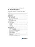
10 For the Enhanced Comm OutAsynchronous data output (UART Transmit) for the Enhanced Comm InAsynchronous data input (UART Receive) for the Enhanced Comm *D OutReady to Send control output (active low) for the Enhanced Comm *D InClear To Send control input (active low) for the Enhanced Comm 7. CP2105 Pin Definitions (Continued)NamePin #TypeDescription*Note: Pins can be left unconnected when not 2. QFN-24 Pinout Diagram (Top View)24232221201912345678910111218171615 1413 GND (optional) CP2105 -GMTop / / / DCD_SCISUSPEND / RI_SCIGNDD+ / / DTR_ECINC / DCD_ECI / VPPSUSPEND / RI_ECIVDDVIOD-RSTVBUSREGINCP2105 Rev. QFN-24 Package SpecificationsFigure 3. QFN-24 Package DrawingTable 8. QFN-24 Package dimensions shown are in millimeters (mm) unless otherwise Dimensioning and Tolerancing per ANSI This drawing conforms to JEDEC Solid State Outline MO-220, variation WGGD except for custom features D2, E2, Z, Y, and L, which are toleranced per supplier Recommended card reflow profile is per the JEDEC/IPC J-STD-020 specification for Small Body Components.