Transcription of D2F - Omron
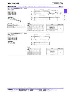
1 1D2FD2 FUltra Subminiature Basic SwitchUltra Subminiature Basic Switch with plenty of terminal variations Incorporating a snapping mechanism made with two highly precise split springs that ensures long durability. Using insertion molded terminalsthat prevents flux penetration. In addition to self-clinching PCB, left-angled, right-angled terminals,2 types of soldering terminals are available. Lineup of 5A type for high load Compliant Model Number Legend D2F -@@@@ 1. Ratings None : 125 VAC 3A 125 VAC 1A (Low operating force) 01 : 30 VDC 5 : 250 VAC 5A2.
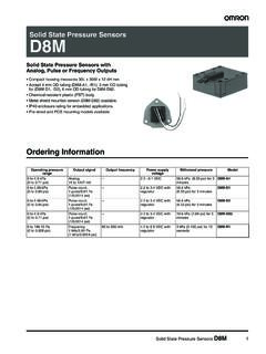
2 Maximum Operating Force (OF) None : N {150 gf} F : N {75 gf}Note. The given values are for pin plunger models Actuator None : Pin plunger L : Hinge lever L2 : Hinge Roller Lever L3 : Simulated roller lever ( ) L30 : Simulated roller lever ( )4. Terminals None : PCB terminals (Straight) -T : Self-clinching PCB terminals -A : PCB terminals (Right-angled) -A1 : PCB terminals (Left-angled) -D3 : Solder terminals -D : Compact solder terminals 1 2 3 4 2D2 FUltra Subminiature Basic SwitchD2 FList of Models*OF are value for Pin Form SPDT Contact Specifications *Please refer to "Using Micro Loads" in "Precautions" for more information on the minimum applicable Note.
3 The above rating values apply under the following test conditions. (1) Ambient temperature: 20 2 C(2) Ambient humidity: 65 5%(3) Operating frequency: 30 operations/min Approved Safety Standard The items shown in the "List of Models" above are not standard approved models. Consult your Omron sales representative for specific models with standard approvals. UL (UL1054) /CSA (CSA ) Ratings3 A 1 A A 5 A Maximum Operating Force (OF) *General Purpose N {150 gf}Low Operating Force N {75 gf}General Purpose N {150 gf}Low Operating Force N {75 gf}General Purpose N {150 gf}Actuator Te r m i n a l s Pin plunger PCB terminals (Standard)
4 D2F D2F-F D2F-01 D2F-01F D2F-5 Self-clinching PCB terminals D2F-T D2F-F-T D2F-01-T D2F-01F-T -PCB terminals (Right-angled) D2F-A D2F-F-A D2F-01-A D2F-01F-A PCB terminals (Left-angled) D2F-A1 D2F-F-A1 D2F-01-A1 D2F-01F-A1 Solder terminals D2F-D3 D2F-F-D3 D2F-01-D3 D2F-01F-D3 Compact solder terminalsD2F-D D2F-F-D D2F-01-D D2F-01F-D Hinge leverPCB terminals (Standard)
5 D2F-L D2F-FL D2F-01L D2F-01FL D2F-5 LSelf-clinching PCB terminals D2F-L-T D2F-FL-T D2F-01L-T D2F-01FL-T -PCB terminals (Right-angled) D2F-L-A D2F-FL-A D2F-01L-A D2F-01FL-A PCB terminals (Left-angled) D2F-L-A1 D2F-FL-A1 D2F-01L-A1 D2F-01FL-A1 Solder terminals D2F-L-D3 D2F-FL-D3 D2F-01L-D3 D2F-01FL-D3 Compact solder terminals D2F-L-D D2F-FL-D D2F-01L-D D2F-01FL-D Hinge rollerlever PCB terminals (Standard)
6 D2F-L2 D2F-FL2 D2F-01L2 D2F-01FL2 -Self-clinching PCB terminals D2F-L2-T D2F-FL2-T D2F-01L2-T D2F-01FL2-T PCB terminals (Right-angled) D2F-L2-A D2F-FL2-A D2F-01L2-A D2F-01FL2-A PCB terminals (Left-angled) D2F-L2-A1 D2F-FL2-A1 D2F-01L2-A1 D2F-01FL2-A1 Solder terminals D2F-L2-D3 D2F-FL2-D3 D2F-01L2-D3 D2F-01FL2-D3 Compact solder terminals D2F-L2-D D2F-FL2-D D2F-01L2-D D2F-01FL2-D Simulated roller lever ( ) PCB terminals (Standard)
7 D2F-L3 D2F-FL3 D2F-01L3 D2F-01FL3 D2F-5L3 Self-clinching PCB terminals D2F-L3-T D2F-FL3-T D2F-01L3-T D2F-01FL3-T -PCB terminals (Right-angled) D2F-L3-A D2F-FL3-A D2F-01L3-A D2F-01FL3-A PCB terminals (Left-angled) D2F-L3-A1 D2F-FL3-A1 D2F-01L3-A1 D2F-01FL3-A1 Solder terminals D2F-L3-D3 D2F-FL3-D3 D2F-01L3-D3 D2F-01FL3-D3 Compact solder terminals D2F-L3-D D2F-FL3-D D2F-01L3-D D2F-01FL3-D Simulated roller lever ( ) PCB terminals (Standard)
8 D2F-L30 D2F-FL30 D2F-01L30 D2F-01FL30 -Self-clinching PCB terminals D2F-L30-T D2F-FL30-T D2F-01L30-T D2F-01FL30-T PCB terminals (Right-angled) D2F-L30-A D2F-FL30-A D2F-01L30-A D2F-01FL30-A PCB terminals (Left-angled) D2F-L30-A1 D2F-FL30-A1 D2F-01L30-A1 D2F-01FL30-A1 Solder terminals D2F-L30-D3 D2F-FL30-D3 D2F-01L30-D3 D2F-01FL30-D3 Compact solder terminals D2F-L30-D D2F-FL30-D D2F-01L30-D D2F-01FL30-D COMNO NCItem ModelD2F modelsD2F-5 modelsD2F-01 models Contact Specifications Crossbar
9 Material Silver alloy Gold alloy Gap (standard value) mm Minimum applicable load (see note) * 100 mA at 5 VDC1 mA at 5 VDCM odelMaximum OperatingForce (OF)Rated voltage D2F models D2F-01 models D2F-5 models (General-purpose) (Low Operating Force) (General-purpose) (Low Operating Force) (General-purpose)Resistive load125 VAC3 A 1 A --30 VDC2 A A A -250 VAC--5 ARated voltage ModelD2F (General-purpose) D2F (Low operating force) D2F-01 125 VAC 3 A 1 A - 30 VDC2 A A A 3D2 FUltra Subminiature Basic SwitchD2 FCharacteristics Note.
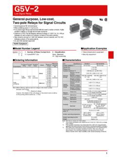
10 The data given above are initial values. * values are at Free Position and Total Travel Position values for pin plunger, and Total Travel Position value for lever. Close or open circuit of the contact is 1ms max.* testing conditions, consult your Omron sales representative. Terminals/Appearances (Unit: mm) Mounting Holes (Unit: mm) ModelD2F-01 models D2F models D2F-5 models Item N (Low operating force) N (General-purpose) N (General-purpose)Permissible operating speed Pin plunger models: 1 mm to 500 mm/s, Lever models: 5 mm to 500 mm/s Permissible operating frequency Mechanical Pin plunger models: 200 operations/min, Lever models: 100 operations/min Electrical