Transcription of Damped 2DOF Model of MIL-S-901D Medium-Weight Shock ...
1 SOUND & VIBRATION/NOVEMBER 2016 7 Damped 2 DOF Model of MIL-S-901D Medium-Weight Shock machine TestNomenclature0- Instant in time just prior to hammer impact0+ Instant in time just after hammer impact2 DOF Two degrees of freedomB Rigid body velocityDim A Dimension A prescribed for MWSM test by MIL-S-901 DEOM Equations of motiong Acceleration due to gravityh Hammer drop heightL Energy lossMDOF Multi degree of freedomMIL-S-901D Military Standard 901 DMWSM Medium-Weight Shock machineN Number of car-building channels used in testnel No energy lossNRL Naval Research LaboratoryR Mass ratio of anvil table to hammer massesSDOF Single degree of freedomSRS Shock Response Spectrum Percent of critical damping expressed as fraction Frequency in radians/sec d Damped frequency in radians/secA two-degree-of-freedom (2 DOF) lumped mass analytical Model of the MIL-S-901D high-impact, Medium-Weight Shock machine (MWSM)5 has been updated to include damping.
2 An initial nondamped analytical Model was developed by Welsh and MWSM test data taken by FMC Corporation4 and testing conducted by the Naval Research Laboratory (NRL)3 has indicated that critical damping in the range of 4-5% exists during the test event. Beyond the addition of damping, the relationship of anvil table kick-off velocity as a function of hammer impact velocity has been further explored. A relationship presented by NRL3 indicated that initial anvil table velocity is of ham-mer impact velocity averaged over all hammer drop heights. This relationship corresponds to a 52% loss of kinetic energy as a result of hammer impact, a significant amount. FMC testing data cor-related more closely to no loss of kinetic energy due to hammer impact.
3 Additional anvil table kick-off velocity relationships are presented here based on the FMC test data and also no loss of energy due to hammer Matlab function was developed based on the 2 DOF MWSM Damped equations of motion. The Matlab function returns time-based displacements, velocities and accelerations for the equip-ment and the anvil table up to the point that the anvil table hits the travel stops of the machine . The function also returns a Shock response spectrum (SRS) of the equipment acceleration during the up- Shock event. The Model makes no attempt to predict rebound Shock to the equipment when the anvil table hits the stops of the a lumped mass 2 DOF Model cannot predict equipment response with the degree of accuracy to that of a transient multi-degree-of-freedom (MDOF), multi-frequency, finite-element Model of the anvil table and the equipment, the 2 DOF Model does provide a quick and easy means to approximate the transient acceleration that the equipment will experience during a MWSM Shock test.
4 The 2 DOF Model transient response could, for example, be used to de-termine a base input acceleration to a more detailed MDOF Model of the equipment. This could be especially helpful, for example, during the preliminary design phase of equipment development when numerous design changes must be evaluated of MWSMThe MIL-S-901D Medium-Weight Shock machine consists of a 3,000-pound pendulum hammer, a 4,400-pound anvil table that the test equipment is mounted to and a 45-ton, reactive mass mounted to the floor with a series of coil springs. A standard test consists of raising the pendulum hammer above horizontal to a specified drop height h and releasing it to rotate underneath the anvil table and strike it from below. The hammer impact results in a nearly instant vertical kick-off velocity of the anvil table, which can travel freely until the table contacts the stops of the mounted to the anvil table experiences a Shock ac-celeration that is transmitted by the anvil table kick-off velocity through a specified number of N flexible car-building channels that are mounted to two ship-building channels.
5 The N car-building channels are specified based on the span of the equipment mount-ing locations (Dimension A) and the weight of the equipment to achieve a frequency in the range of the hull of a test consists of releasing the hammer, which is raised above horizontal by h feet, resulting in a hammer-to-anvil table contact velocity of approximately 2gh. The original objective of the test was to achieve an initial kick-off velocity of the anvil table of six feet per second. After hammer impact, the anvil table travels up-ward until it hits the stops of the machine , which are set to either in or in for a standard MIL-S-901D test. When the anvil table contacts the stops, the impact results in a rebound Shock , the severity of which depends on phasing between the anvil table and equipment motions at the point of impact.
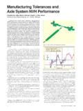
6 A schematic of the MWSM is shown in Figure 2 DOF MWSM ModelThe initial 2 DOF analytical Model was developed by Welsh and In this Model , the Shock machine was assumed to have no damping (z = 0). The same nondamped Model was also described by Scavuzzo and The presence of damping was observed during testing conducted by the Naval Research Labora-tory3 and by FMC The analytical 2 DOF Model documented J. Edward Alexander, BAE Weapon Systems, Minneapolis, MinnesotaFigure 1. MIL-S-901D Medium-Weight Shock SOUND & VIBRATION/NOVEMBER 2016here includes damping represented as a percent of critical illustrated in Figures 2 and 3, the equipment is represented as a single lumped mass. The hammer, anvil table and equip-ment masses are indicated by m1, m2 and m3, respectively, with coordinates y1, y2 and y3, respectively, in Figure 3.
7 The stiffness k represents the combined stiffness of N car-building channels that support the equipment. Damping is represented as a percent of critical damping, indicated by z. The system, initially at rest, is excited by the hammer impact to the underside of the anvil table with an upward velocity of V1 just prior to impact, designated as time, t = 0-. The impact results in an initial kick-off velocity of the anvil table, designated as an initial condition V 2 in the analytical Model at time, t = 0+, just after hammer relationship of the anvil table kick-off velocity as a func-tion of the hammer impact velocity, V 2 = f (V1), is developed from conservation of momentum and conservation of energy given by Eqs. 1 and 2, respectively:Conservation of momentum: Conservation of energy:The velocity ratio V 2/V1, given by Eq.
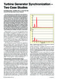
8 3, is solved from and 2:where R = m2/m1and L is the energy loss during the velocity ratioV 2/V1 was determined by testing performed by Clements at the Naval Research Figure 4 is a plot of the data from Ref. 3, where a straight line fit of the data is given by Eq. 4:When L is solved in Eq. 3 using , the resulting energy loss is L is a significant It is noted that if holds, the instant after the hammer strikes anvil table, the hammer continues upward with a positive upward velocity. High-speed video was taken by BAE Systems to determine if this was the case. The video showed that the hammer did not continue to move upward after impact. The hammer appeared to stop instantly at impact and immediately fall downward, away from anvil table.
9 As an additional system check, V2=f (V1) was determined from FMC MWSM test data,5 resulting in a relationship for V2 given by Eq. 5, which is a linear least-squares fit through the FMC data points in Figure third option is offered assuming there is no loss of kinetic energy due to the collision. The resulting relationship for no energy loss is given by Eq. three relationships for V2 = f (V1) represented by Eqs. 4, 5 and 6 are plotted in Figure 5. The individual data points plotted correspond to FMC test results. The no energy loss relationship (Eq. 6) appears to also be consistent with the individual FMC data points. The relationship indicated by Eq. 4 does not fit the FMC plotted data, except possibly a at high hammer impact velocities above 18 ft/sec.
10 Inasmuch as the FMC linear data fit given by Eq. 5 does not go through zero for zero hammer velocity, it is suggested that below hammer velocities of 8 ft/sec that Eq. 6 be used. Development of MWSM Damped Equations of MotionThe Damped equations of motion (EOM) were developed with an approach similar to those used in References 1 and 2. Damping has been observed during MWSM Shock tests as documented in References 3 and 4. The EOMs developed herein include damping characterized by a percent of critical damping for the entire system. The equations of motion are developed for equipment and the anvil table immediately after hammer impact has occurred. Both the equipment and the anvil table masses are placed into dynamic force equilibrium by setting S Forces = 0 as illustrated in Figure 6.