Transcription of Daniel 3814 - Emerson
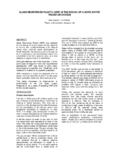
1 Datasheet August 2018 Daniel 3814 Liquid Ultrasonic Flow MeterLiquid Ultrasonic Flow Intelligence at Work Designed for custody transfer applications, the new Daniel 3814 Liquid Ultrasonic Flow Meter is engineered to deliver highly accurate measurement of liquid hydrocarbons in accordance with API Chapter and OIML R117. The advanced four-path meter offers exceptional rangeability and linearity to minimize lost and unaccounted for liquids. The meter measures the transit times of ultrasonic pulses passing through the liquid in four parallel planes. Integrally mounted ultrasonic transducers transmit and receive signals with the difference in transit times of the downstream and upstream pulses directly proportional to the measured fluid velocity.
2 With accurate upstream/downstream transit time measurement and no moving parts, the meter is ideal for bi-directional measurement. Powerful next-generation Daniel 3810 Electronics work with the meter to significantly increase the sampling rate and provide high-volume data capture, including extensive hourly and daily logs. The streamlined electronics feature a plug-in ready, integrated CPU and I/O board assembly and a local LCD display (optional) to increase reliability, simplify maintenance and facilitate future can easily monitor and troubleshoot the 3814 meter in real time from a PC or laptop. Daniel MeterLink Diagnostics Software is an intuitive user interface that provides critical information, including functional, process and systematic diagnostics, to enhance reliability and reduce measurement 1.
3 Daniel 3814 Liquid Ultrasonic Flow Meter3814 Liquid Ultrasonic Flow MeterTypical Application Custody transferApplication Sites Floating production storage and off-loading (FPSO) Offshore platforms Crude oil pipelines Refined product pipelines Ethane/LPG/gasoline/diesel/aviation fuel Loading and off-loading ships, barges and railcars Tank farmsFeatures and Benefits Custody transfer accuracy and repeatability with high capacitydata logs for accountability and auditing Measurement stability reduces uncertainty of meter factor Full bore design eliminates incremental pressure drop andreduces energy costs No moving parts reduce maintenance costs and eliminate periodic calibration unless required by local metrology authorities or company guidelines Field replaceable non-wetted transducers Wide flow range provides design flexibility Bi-directional flow capabilities simplify installation and reduce startup time 3810 Series Electronics provide fast sampling and output, an expandable electronics platform.
4 And an archive data log with detailed hourly and daily information Local LCD display (optional) with up to ten user-selectable scrolling variables Daniel MeterLink diagnostics software allows access to expert flow analysis and provides an intuitive view of meter health Predictive diagnostics are communicated and variable information is processed allowing plant personnel to quickly detect and respond to abnormal situations to avoid process upsets and unscheduled downtime The Daniel 3814 meter is part of Emerson 's broad range of intelligent field devices that power the PlantWeb digital plant architecture Daniel 2 Standard SpecificationsPlease consult a Daniel technical specialist if requirements are outside of the listed specifications.
5 Improved performance for other product and material offerings may be available depending on the application.(1) Consult factory for sizes above DN600 (24-in), pressure ratings greater than PN 150 (ANSI 900) or other flange options.(2) It is the equipment user s responsibility to select the materials suitable for the intended Ratings Line Sizes DN100 to DN600 (4-in to 24-in)(1) Operating Product Temperature Standard: -50 C to +100 C (-58 F to +212 F) Optional: -50 C to +150 C (-58 F to +302 F)Operating Pressure Range 0 to 155 Bar (0 to 2250 psig)(1)Flanges Raised Face and Ring Type Joint (RTJ) for PN 20, 50, 100 and150 (ANSI 150, 300, 600 and 900)(2) Higher ANSI ratings available upon requestNACE and NORSOK Compliance Designed for NACE compliance(2) NORSOK available upon requestElectronics Ratings Operating Temperature -40 C to +60 C (-40 F to +140 F)Operating Relative Humidity Up to 95% non-condensingStorage Temperature -40 C to +85 C (-40 F to +185 F) Electronic Housing Options Integral mount (standard) Remote mount (optional) with m (15 ft) cable Required for process temperature above +60 C (+140 F)
6 Meter SpecificationsCharacteristics Transit-time based measurement Full bore spool piece meter body Four-path (eight transducer) chordal designMeter Performance Linearity is of measured value over a to m/s (4 to40 ft/s) range Linearity is of measured value over a to m/s (2 to40 ft/s) range (optional)Uncertainty of Meter Factor < (API MPMS, Chapter 5, Section 8, Table B-1)Velocity Range to m/s (2 to 40 ft/s) with an extended range to m/s (1 to 48 ft/s)Calibration ISO 17025 certified flow calibration laboratory available forall meters Additional calibration options available upon requestElectronics PerformancePower VDC to 36 VDC 8 watts typical; 15 watts maximumAugust 2018 Liquid Ultrasonic Flow Specifications Body and FlangeCast ASTM A352 Gr LCC Carbon Steel(1) -46 C to +150 C (-50 F to +302 F) ASTM A351 Gr CF8M 316 Stainless Steel-46 C to +150 C (-50 F to +302 F) ASTM A351 Gr CF8M 316L Stainless Steel-46 C to +150 C (-50 F to +302 F) ASTM A995 Gr 4A Duplex Stainless Steel(2)-50 C to +150 C (-58 F to +302 F)Forgings ASTM A350 Gr LF2 Carbon Steel(1) -46 C to +150 C (-50 F to +302 F) ASTM A182 Gr F316 Stainless Steel -46 C to +150 C (-50 F to +302 F) ASTM A182 Gr F316L Stainless Steel -46 C to +150 C (-50 F to +302 F) ASTM A182 Gr F51 Duplex Stainless Steel(2)-50 C to +150 C (-58 F to +302 F)
7 ASTM A105 Carbon Steel-29 C to +150 C (-20 F to +302 F)Enclosure Housing ASTM B26 Gr T6 Aluminum ASTM A351 Gr CF8M Stainless SteelTransducer Components Transducer Housing O-ring Standard: Nitrile Butadiene Rubber (NBR) Other materials availableTransducer Housing ASTM A479 316L Stainless Steel with proprietary matchinglayer material INCONEL ASTM B446 (UNS N06625) Gr 1 (optional)Cable Gland Chloroprene/Nitrile Rubber Materials of ConstructionPaint SpecificationsBody and FlangeCarbon Steel Body 2 coat paint; zinc primer and acrylic lacquer topcoat (standard)Stainless Steel or Duplex Body Paint (optional) Enclosure HousingAluminum Chromate conversion coated with a polyurethane enamel Stainless Steel PassivatedTable 1A: Body and Flange Maximum Pressure Ratings by Construction Materials (bar Meter Sizes DN100 to DN600)(3)PNCast Carbon SteelForged Carbon SteelCast 316 SS, 316L SS,Forged 316 SSForged 316L SSDuplex 1B.
8 Body and Flange Maximum Pressure Ratings by Construction Materials (psi Meter Sizes 4-in to 24-in)(3)ANSI ClassCast Carbon SteelForged Carbon SteelCast 316 SS, 316L SS, Forged 316 SSForged 316L SSDuplex SS15029028527523029030075074072060075060 01,5001,4801,4401,2001,5009002,2502,2202 ,1601,8002,250(1) Impact tested per specified ASTM standard. (2) A995 4A material is not available in Canada.(3) Pressure rating information is for -29 C to +38 C (-20 F to +100 F). Other temperatures may reduce the maximum pressure rating of the 4 Table 2A: Flow Ranges (Metric Units)Nominal Meter Size (DN)Meter ID (mm)Pipe ScheduleFluid Velocity (m/s)Flow Rate (m3/hr) ,4171, ,2332, ,1703, ,0046, ,3347, ,8719, ,38313,660 Table 2B.
9 Flow Ranges (US Customary Units)Nominal Meter Size (in)Meter ID (in)Pipe ScheduleFluid Velocity (ft/s)Flow Rate (BPH) 40240481132,2672, 40240482575,1466, 40240484468,91010, 402404870214,04516, 402404899719,93623, 40240481,57431,47437, 40240481,99239,83947, 40240482,47549,50459, 40240483,58071,59985,919 Standard Flow RangesAugust 2018 Liquid Ultrasonic Flow 1000 2000 3000 4000 5000600 cSt168 cStReynolds Number (Re)% ErrorTypical Meter Performance The charts below represent meter performance, on two higher viscosity fluids, showing meter error based on Reynolds number (Re) and flow rate (m3/hr).High Viscosity Flow Conditioning RecommendationsRe% ErrorDaniel 3814 (1) The analog-to-digital conversion accuracy is within of full scale over the operating temperature range.
10 (2) A 24 volt DC power supply is available to provide power to the sensors.(3) AI-1 and AI-2 are electronically isolated and operate in sink mode. The input contains a series resistance for HART Communicators to be connected for sensor configuration.(4) The analog output zero scale offset error is within of full scale and gain error is within of full scale. The total output drift is within 50 ppm of full scale per 4: CPU Module I/O Connections (maximun wire gauge is 18 AWG)I/O Connection TypeQtyDescriptionSerial CommunicationsSerial RS232/RS485 Port 1 Modbus RTU/ASCII 115 kbps baud rateEthernet Port (TCP/IP) 100 BaseT1 Modbus TCPD igital Input(1)Contact Closure1 Status Single polarity Analog Inputs(2)4-20 mA2 AI-1 Temperature(3) AI-2 Pressure (3)Frequency/Digital OutputsTTL/Open Collector3 User ConfigurableAnalog Output(2, 4)4-20 mA2 Independently configurable analog output HART 7 Compliant, consult factory for HART 5 Local LCD DisplayInput/OutputThe 3810 Series Electronics offer an optional local LCD display that utilizes three lines to indicate the variable name, variable value and engineering units.