Transcription of Data Acquisition Fundamentals - Measurement …
1 White Paper by Measurement Computing, Inc. Copyright 2013 Measurement Computing, Acquisition Fundamentals : Making Accurate Temperature Measurements with Thermocouples, Thermistors and RTD SensorsPage 2 Measurement Computing | 1-800-234-4232 | | Temperature is the most common physical Measurement engineers and scientists make. From highly accelerated life testing (HALT)/highly accelerated stress screening (HASS) to dynamometer test cells and microprocessor validation, temperature measurements play a key role in a vast array of applications. While modern systems have addressed the complex hurdles of temperature Measurement and simplifi ed the process for users, understanding the theories, operation, and inherent pitfalls of temperature measurements is still helpful.
2 This white paper covers these topics in-depth for the most widely-used temperature transducers: thermocouples, resistance temperature detectors (RTDs), and thermistors. Each sensor has advantages and disadvantages based on the application needs (see Table 1).ThermocoupleRTDT hermistorTemperature rangeBest(-200 C to 1700 C)Better(-200 C to 800 C)Good(-55 C to 300 C)AccuracyGoodBetterBestCostBestGoodBett erSensitivityGoodBetterBestTable 1: Common Temperature sensors, the most common temperature transducers, are inexpensive, cover a wide temperature range, and are rugged, but they are the least accurate of the three temperature transducers. RTDs are more expensive than thermocouples but offer greater accuracy and stability.
3 Thermistors are less expensive than RTDs, more accurate than thermocouples, and offer excellent sensitivity, but they operate over a fairly small temperature each type of transducer has advantages and disadvantages depending on the application, each also presents different requirements for a Measurement system. The thermocouple, for example, is a simple device two wires of different metals welded together at one end. But this simple device poses many challenges to a Measurement system, including the need for amplifi cation, fi ltering, and cold-junction compensation (CJC).Page 3 Measurement Computing | 1-800-234-4232 | | and thermistors pose different challenges.
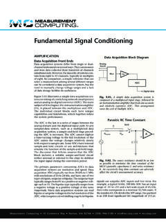
4 Because they are both resistive devices, these Measurement sensors need a current source to convert resistance to a voltage. RTDs also require circuitry to maximize accuracy and the Fundamentals of each temperature transducer allows users to choose the best transducer and the right Measurement for an Temperature MeasurementThermocouples are the most widely used yet least-understood of all temperature measuring devices. When connected in pairs, they are simple and effi cient sensors that output an extremely small DC voltage proportional to the temperature difference between the two junctions in a closed thermoelectric circuit (Refer to Figure 1). Cu -NiConstantanCopperCopperCopperCopperT10 C (32 F)T2-270 C to +400 C(-454 F to +752 F)MeasuredenvironmentaltemperatureCu -NiConstantanCopperCopperReferencetemper atureDVMOpen tomeasurevoltageDigital Voltmeteroutput proportional to thedifference between T1 and T2 Type TT1T2 Fig.
5 1: Type T Basic Thermocouple Circuit. A classic thermocouple Measurement system requires two sensors: one for the environment being measured and the other for a reference junction, normally held to 0 C (32 F).One junction is normally held at a constant reference temperature while the opposite junction is immersed in the environment to be measured. The principle of operation depends on the unique value of thermal electromotive force (EMF) measured between the open ends of the leads and the junction of two dissimilar metals held at a specifi c temperature. Named after its discoverer, Thomas Johann Seebeck, the principle is called the Seebeck effect. The amount of voltage present at the open ends of the sensor and the range of temperatures the device can measure depend on the Seebeck The Gradient Nature of ThermocouplesThomas Seebeck discovered that an electric current is induced in a conductive material when exposed to a temperature 4 Measurement Computing | 1-800-234-4232 | | cient, which in turn depends on the chemical composition of the thermocouple wire.
6 The Seebeck voltage is calculated from the following equation: eAB = TWhere: eAB = Seebeck voltageT = temperature at the thermocouple junction = Seebeck coeffi cient = a small change in voltage corresponding to a small change in temperatureEquation 1: Seebeck junctions alone do not generate voltages. The voltage or potential difference that develops at the output (open) end is a function of both the temperature of the junction T1 and the temperature of the open end T1 . T1 must be held at a constant temperature, such as 0 C, to ensure that the open-end voltage changes in proportion to the temperature changes in T1. In principle, a thermocouple can be made from any two dissimilar metals, such as nickel and iron.
7 In practice, however, only a few thermocouple types have become standard because their temperature coeffi cients are highly repeatable, they are rugged, and they output relatively small voltages. The most common thermocouple types are called J, K, T, and E, followed by N28, N14, S, R, and B (Refer to Table 2). In theory, the junction temperature can be inferred from the Seebeck voltage by consulting standard tables. In practice, however, this voltage cannot be used directly because the thermocouple wire connection to the copper terminal at the Measurement device itself constitutes a thermocouple junction (unless the thermocouple lead is also copper) and produces another thermal EMF that requires using the Seebeck effect should keep in mind that they are measuring the temperature difference between the two ends.
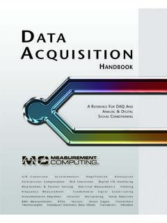
8 A reference point must be established to turn the relative Measurement of a thermocouple temperature gradient into the absolute Measurement at the tip of the to popular belief, thermocouple junctions alone do not generate 5 Measurement Computing | 1-800-234-4232 | | early Measurement systems, the most convenient reference point was an ice bath, which provided a consistent 0 C reference. In modern Measurement systems, ice baths are replaced with temperature sensing ICs and software compensation. To better explain thermocouple theory, this paper will explain the classic ice-bath method fi rst and then discuss software compensation methods cold-junction thermocouple immersed in an ice bath and connected in series with the measuring thermocouple is the classical method used to compensate for the EMF at the instrument terminals (Refer to Table 2).
9 TypeMetal+ -Standard color code+ - /double foot 20 AWGS eebeck coeffi cient S( V/ C) @ T( C) C standard wire errorNBS specifi ed materials range* ( C)BPlatinum-6% RhodiumPlatinum- 30% Rhodium to to 1820**ENickel-10% ChromiumConstantan to to 1000 JIronConstantan to to 760 KNickel- 10% ChromiumNickel to to 1372N (AWG 14)NicrosilNisil 39600 0 to 1300N (AWG 28)NicrosilNisil -270 to 400 RPlatinum-13% RhodiumPlatinum to to 1768 SPlatinum-10% RhodiumPlatinum to to 1768 TCopperConstantan to to 400W-ReTungsten- 5% RheniumTungsten- 26% Rhenium 0 to 2320* Material range is for 8 AWG wire; decreases with deceasing wire size ** Type B double-valued below 42 C curve fi t specifi ed only above 130 CTable 2: Common Thermocouple Types.
10 The National Institute of Standards and Technology (NIST) thermocouple EMF tables publish the EMF output of a thermocouple based on a corresponding reference thermocouple junction held at 0 6 Measurement Computing | 1-800-234-4232 | | this example, both copper leads connect to the instrument s input terminals. An alternative method uses a single thermocouple with the copper/constantan connection immersed in the reference ice bath, which is also represented in Figure 2. The thermocouple junction J2 in the ice bath contributes a small EMF that subtracts from the thermocouple J1 EMF, so the voltage measured at the instrument or data - Acquisition system input terminals corresponds accurately to the NIST tables.